This post shows how you can output VGA signals to a monitor, turning your Uno (or similar) processor into a "video card". Example:

The only extra hardware used here was 5 resistors, and a DB15 socket to plug the monitor cable into:

Watch live demo:
To understand how it all works, we need to look at how VGA signal timing works.
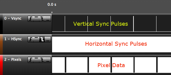
There are 5 signals being sent to the monitor:
For timing reasons we don't have time to output separate red, green, and blue levels, so they are physically connected at the socket, giving white.
[EDIT] However see follow-up post showing how you can do colour.
Thus there are three important signals now:
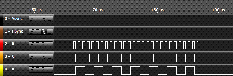
On the logic analyzer we can see an overall view:
The two lower signals are just blocks of white right now - we'll have to zoom in to see them better.
This diagram shows the various timings involved:
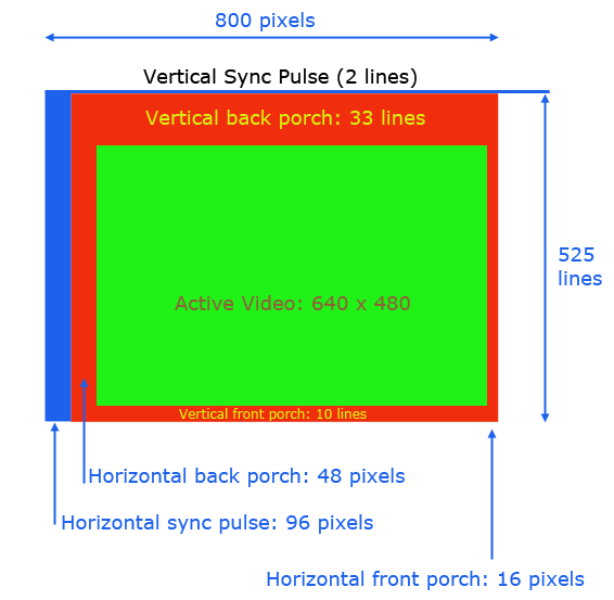
Assuming for discussion that we have a 640 x 480 resolution screen, the hardware needs a little extra time to move the electron beam (in the days when we used CRT monitors) from one side of the screen to the other, and from the bottom back to the top. These are the front and back "porches" (don't ask me why the name).
The screen refresh starts off with a vertical sync pulse, which tells the monitor to reset to the top of the screen. It has the "back porch" number of lines to get ready to start drawing, and to draw a blank area at the top. Then it draws the image, and has the "front porch" extra lines to draw the blank information at the bottom of the screen.
Meanwhile, for each line, there is a horizontal sync pulse which signals the start of that line, followed by another delay to give the beam time to get ready, then it draws the line, and has some extra "front porch" time over for the blank part at the end of the line.
Let's start with the vertical sync pulses. In fact, we'll show how all the timing data can be derived from three figures:
So what is the refresh rate? It's the rate at which the entire screen is redrawn. If you ever looked at Windows screen resolution you probably saw something like this:

That's the refresh rate: 60 Hz (60 times a second). This figure was probably originally chosen because it is the mains frequency in the USA, so that would minimize the artifact of mains hum bars appearing on the screen, in the days of CRT monitors.
The other figure of interest is the screen resolution, for example:

In our case we are going for the minimum we can (640 x 480) and seeing where those figures lead us.
Starting with the refresh rate, a 60 Hz refresh rate will require a "vertical sync" pulse 60 times a second, or a period of 1/60 (16.66 ms).
This screenshot shows that the vertical sync pulses are indeed (nearly) 16.66 ms apart:

Observed figures might differ from theory by about 1% due to the internal clock of the processor not being 100% accurate.
This code, in setup, generates the vertical sync pulses:
The clock period is 62.5 ns (1/16000000). By applying a prescaler of 1024 the timer counts up once every 64 µs. So to get a period of 1/60 of a second (16666 µs) we need to count up to 260 (16666 / 64 = 260). Since the timer counts are zero-relative we set OCR1A to count up to 259. This sets the frequency of Timer 1.
Then we need to set the pulse width by putting the correct value in OCR1B. We want a pulse width of two lines. One line is 1 / 60 / 525, namely 31.7 µs. So two lines would be 63.4 µs. This is close enough to exactly one timer count (64 µs). So OCR1B is set to zero (being zero-relative, making it zero gives a count of 1).
Timer 1 is configured to "clear B on compare" which effectively means that it toggles the output pin (D10 on the Uno) so it is high for the duty cycle width (64 µs) and low the rest of the time. If you wanted the opposite sync pulse polarity, change CLEAR_B_ON_COMPARE to SET_B_ON_COMPARE.
We can see from the logic analyzer output that the vertical sync pulses are indeed happening at 60 Hz, and that the pulse width is 63.9 µs.
So far so good ...

The timer is also set up to generate an interrupt, which is used to tell the code that we are starting another vertical cycle, by setting the line count to zero:
Horizontal sync pulses tell the monitor when to start drawing each line.
To calculate the horizontal sync frequency we need to divide the overall frame rate (60 Hz) by the number of total lines (525 if you count the sync pulse itself, and the front and back porches).
In other words:
We also need to know the sync pulse width. That is documented to be 96 pixels, so we need to know the width of one pixel. That would be the figure above, divided by 800 (being the total screen width including the sync pulse, and front and back porches).
Thus that is:
So our pixel width is 39.68 ns and the pixel clock is 25.2 mHz.
The horizontal sync pulse width is 96 pixels, so we want a pulse of:
Now we are ready to set up the timer for the horizontal sync pulses:
The clock period is 62.5 ns (1/16000000). By applying a prescaler of 8 the timer counts up once every 0.5 µs. So to get a period of 32 µs we need to count up to 64 (32 / 0.5 = 64). Since the timer counts are zero-relative we set OCR2A to count up to 63. This sets the frequency of Timer 2.
Then we need to set the pulse width by putting the correct value in OCR2B. We want a pulse width of 96 pixels (3.8 µs). So OCR2B is set to 7 (being zero-relative, making it 7 gives a count of 8, which is 4 / 0.5).
Again, if you wanted the opposite sync pulse polarity, change CLEAR_B_ON_COMPARE to SET_B_ON_COMPARE.
We can see from the logic analyzer output that the horizontal sync pulses are indeed happening every 31.9 µs, and that the pulse width is 4 µs.

The timer is also set up to generate an interrupt, which has the sole purpose of waking the processor up from sleep, so it can draw each line with exactly the same delay after the pulse. If it wasn't asleep, there would be a variation of two to three clock cycles (since an interrupt cannot occur during a single instruction) and this gives very bad-looking "jitter" on the screen.
Now things get tricky ...
Let's see how long we have to draw 640 pixels:
It just can't be done on this processor. The clock period itself is only 62.5 ns, so there is no way we can output a pixel every 39.68 ns (that is: 25396.82 / 640 = 39.68).
The fastest way we can get bits "out the door" is using the SPI hardware. That can run at a maximum clock rate of twice the system clock, that is, one pixel every 125 ns. So we will have to settle for having the pixels 4 times as wide. A horizontal resolution therefore of 160 pixels. Since we will display 8-pixel characters, that gives us 20 characters per line.
We also don't have enough memory to even hold those pixels all at once. Even at a bit per pixel, that would be:
Since the processor only has 2048 bytes of memory there is no way we can hold any sort of bitmap. So, we will have to decode text into pixels "on the fly" for every line. This itself takes time. Especially since to hold 256 characters as 8 bytes each (8 x 8 pixels) takes 2048 bytes. So we can't hold the font data in RAM either.
So, the fonts have to go into PROGMEM (program memory) and be accessed on the fly for every line, using "program memory read".
I am using the USART in SPI mode. This is double-buffered so hopefully should give us a slight edge in performance. Even doing that isn't perfect because of what I have read of as the "9th bit problem". That is, the USART sends out one additional "high" bit per byte. This looks very annoying if you are doing white-on-black because there is a white bar between each letter. To hide this, we invert the fonts to give black on white text. Then the extra bit just looks like a space between the letters.
The line drawing is done in doOneScanLine which is called directly after being woken from sleep. As mentioned above, the sleep is necessary to make sure that we start each scan line at exactly the same time after the sync pulse:
Inside doOneScanLine we check if we have done the back porch lines, and if not, exit. If it is time to draw something, we pre-load some pointers (to save time) and then execute this loop:
For each byte in the current "message" (text) line, we look up the relevant pixel (font) data in program memory, and stuff that into the USART "send" register.
The font data has been deliberately structured to save a multiply by 8. Initially I had each character together (so from one letter to the next was 8 bytes, since it takes 8 bytes per character). Unfortunately, multiplying by 8 (even if you do it via a shift left) just took too long. So instead, the font table was restructured so all the data per scan line was together, not all the data for one letter. Also the font is pre-inverted (to white on black) to save doing that at drawing time.
There aren't any delays or tests for "is SPI ready?" in that loop. Let's see why not. The code for that loop is:
Apart from the initial setup at the start of the loop (done once) there are 17 cycles in the loop. I added the cycle count for each instruction at the start of the line.
Now it takes 16 cycles to output 8 bits (since each bit takes 125 ns) so each byte is transferred in 16 cycles, and the loop above takes 17. So that gives us a 1-cycle gap between letters, which apparently we get anyway because of the way that SPI works. So the loop is exactly the right length.
One scan line being drawn:

Note that the thinnest pixel (arrowed) is 125 ns long. That's the shortest we can do.
The finished code is remarkably short. This is what it looks like without any ability to accept incoming text changes:
This is the file "screenFont.h" which has the font patterns in it:
To compile you also need the timer helpers library:
The TimerHelpers.h file can be downloaded from:
http://gammon.com.au/Arduino/TimerHelpers.zip
The problem with this sketch is, it's very busy. Almost all its time is spent refreshing the screen. There is a horizontal sync pulse every 32 µs and then it spends 25 µs drawing the pixels. So, not much time over to do other stuff. (There's a bit, because during the vertical retrace we aren't drawing pixels).
So really, we need to have a second processor that actually does the useful work (eg. monitor the aquarium, do the burglar alarm, measure the temperature) and send the text to the VGA output sketch for displaying.
To achieve this, the only real way is to use I2C. A pin needed for SPI (pin 10) is in use by Timer 1 for Vsync. The serial hardware is in use by the output routines. So that leaves I2C.
In the "communicating" version I have set up a I2C request event, like this:
The slave address is currently 42, but you can change that to any free address (just make sure the sending end uses the same address).
When incoming I2C data arrives it is directed to a "state machine" that decodes the text and puts it into the "message" array (30 lines x 20 characters). To make it more useful you can send a few "control" characters, namely:
The newline character also scrolls the display, by moving everything up one line, if it occurs with the cursor on the 30th line.
Unfortunately incoming data can tend to make the display "glitch" as the interrupt stops the display drawing in the middle of a line. Attempts to correct that have not been a big success. If you turn off interrupts long enough to stop the glitching you then have the problem of incoming data being dropped. So I think it's better to have the occasional glitch, and see everything, than have important messages disappear.
To try to minimize this I increased the I2C clock rate in the sending "test" sketch, so that we transfer the message to the VGA output sketch as fast as possible.
Example sending sketch:
To save a lot of repetition the sending is done inside the sendString function, which does the begin and end transmission as well. Note that I2C has a buffer size of 32, so don't try to send more than 32 bytes in one send. (So, a line at a time would be a good compromise).
This shows how to connect up the DB15 connector (socket) that you plug your VGA cable into:

The 470 ohm resistors are there to convert the 5V output from the Uno into 0.7V for the analog pixel data. This is because there is a 75 ohm resistor inside the monitor, so the 470 ohm resistors form voltage dividers:
688 mV is close enough to the required 700 mV.
I'm not sure about the 68 ohms resistors for the two TTL lines (sync lines) but I have seen them suggested on other web sites.
Of course, if you prefer green or blue output, just omit the wire to the appropriate pins. You can have red/green/blue or some combination (cyan/magenta/yellow/white).
The three wires on the left are for connecting up to another processor to feed this one with the data to be displayed.
The VGA Output sketch above, plus the font file, and the timers helper file, are all in the .zip file here:
http://gammon.com.au/Arduino/VGA_output.zip
I've had suggestions to "improve" the sketch by adding colour. Hopefully I've explained why you can't simply do that, without sacrificing something. The output loop is already very tight, with only one clock cycle to spare.
Let's say, for example, that you wanted to send colour. First you would need to have 3 pixel pins (reg/green/blue), so that rules out using SPI. You would have to manually load up (bit bang) a register with all 3 colours. This would be a lot slower. Also you would need to keep the colour information somewhere.
And to do graphics you would need to keep the "bitmap" somewhere. Even to store the bits for 160 x 480 x 4 bit colour would require 160 * 480 * 4 bits = 307200 bits which is 38400 bytes. Well there simply isn't that much memory in the processor. You have 2048 bytes.
The only extra hardware used here was 5 resistors, and a DB15 socket to plug the monitor cable into:
Watch live demo:
VGA Timing
To understand how it all works, we need to look at how VGA signal timing works.
There are 5 signals being sent to the monitor:
- Vertical Synchronization (sync) (TTL)
- Horizontal Synchronization (sync) (TTL)
- Red analog data (0 to 0.7V)
- Green analog data (0 to 0.7V)
- Blue analog data (0 to 0.7V)
For timing reasons we don't have time to output separate red, green, and blue levels, so they are physically connected at the socket, giving white.
[EDIT] However see follow-up post showing how you can do colour.
Thus there are three important signals now:
- Vertical sync pulses
- Horizontal sync pulses
- Pixel data
On the logic analyzer we can see an overall view:
The two lower signals are just blocks of white right now - we'll have to zoom in to see them better.
Overall structure
This diagram shows the various timings involved:
Assuming for discussion that we have a 640 x 480 resolution screen, the hardware needs a little extra time to move the electron beam (in the days when we used CRT monitors) from one side of the screen to the other, and from the bottom back to the top. These are the front and back "porches" (don't ask me why the name).
The screen refresh starts off with a vertical sync pulse, which tells the monitor to reset to the top of the screen. It has the "back porch" number of lines to get ready to start drawing, and to draw a blank area at the top. Then it draws the image, and has the "front porch" extra lines to draw the blank information at the bottom of the screen.
Meanwhile, for each line, there is a horizontal sync pulse which signals the start of that line, followed by another delay to give the beam time to get ready, then it draws the line, and has some extra "front porch" time over for the blank part at the end of the line.
Vertical Sync
Let's start with the vertical sync pulses. In fact, we'll show how all the timing data can be derived from three figures:
- The screen refresh rate (eg. 60 Hz)
- The screen resolution (eg. 640 x 480)
So what is the refresh rate? It's the rate at which the entire screen is redrawn. If you ever looked at Windows screen resolution you probably saw something like this:
That's the refresh rate: 60 Hz (60 times a second). This figure was probably originally chosen because it is the mains frequency in the USA, so that would minimize the artifact of mains hum bars appearing on the screen, in the days of CRT monitors.
The other figure of interest is the screen resolution, for example:
In our case we are going for the minimum we can (640 x 480) and seeing where those figures lead us.
Starting with the refresh rate, a 60 Hz refresh rate will require a "vertical sync" pulse 60 times a second, or a period of 1/60 (16.66 ms).
This screenshot shows that the vertical sync pulses are indeed (nearly) 16.66 ms apart:
Observed figures might differ from theory by about 1% due to the internal clock of the processor not being 100% accurate.
Generating vertical sync pulses
This code, in setup, generates the vertical sync pulses:
  // Timer 1 - vertical sync pulses
  pinMode (vSyncPin, OUTPUT);
  Timer1::setMode (15, Timer1::PRESCALE_1024, Timer1::CLEAR_B_ON_COMPARE);
  OCR1A = 259;  // 16666 / 64 µs = 260 (less one)
  OCR1B = 0;    // 64 / 64 µs = 1 (less one)
The clock period is 62.5 ns (1/16000000). By applying a prescaler of 1024 the timer counts up once every 64 µs. So to get a period of 1/60 of a second (16666 µs) we need to count up to 260 (16666 / 64 = 260). Since the timer counts are zero-relative we set OCR1A to count up to 259. This sets the frequency of Timer 1.
Then we need to set the pulse width by putting the correct value in OCR1B. We want a pulse width of two lines. One line is 1 / 60 / 525, namely 31.7 µs. So two lines would be 63.4 µs. This is close enough to exactly one timer count (64 µs). So OCR1B is set to zero (being zero-relative, making it zero gives a count of 1).
Timer 1 is configured to "clear B on compare" which effectively means that it toggles the output pin (D10 on the Uno) so it is high for the duty cycle width (64 µs) and low the rest of the time. If you wanted the opposite sync pulse polarity, change CLEAR_B_ON_COMPARE to SET_B_ON_COMPARE.
We can see from the logic analyzer output that the vertical sync pulses are indeed happening at 60 Hz, and that the pulse width is 63.9 µs.
So far so good ...
The timer is also set up to generate an interrupt, which is used to tell the code that we are starting another vertical cycle, by setting the line count to zero:
ISR (TIMER1_OVF_vect)
  {
  vLine = 0;
  messageLine = 0;
  backPorchLinesToGo = verticalBackPorchLines;
  } // end of TIMER1_OVF_vect
Horizontal sync
Horizontal sync pulses tell the monitor when to start drawing each line.
To calculate the horizontal sync frequency we need to divide the overall frame rate (60 Hz) by the number of total lines (525 if you count the sync pulse itself, and the front and back porches).
In other words:
(1/60) / 525 * 1e6 = 31.74 µs
We also need to know the sync pulse width. That is documented to be 96 pixels, so we need to know the width of one pixel. That would be the figure above, divided by 800 (being the total screen width including the sync pulse, and front and back porches).
Thus that is:
((1/60) / 525 * 1e9) / 800 = 39.68  ns
1 / (((1/60) / 525 * 1e6) / 800) = 25.2 MHz
So our pixel width is 39.68 ns and the pixel clock is 25.2 mHz.
The horizontal sync pulse width is 96 pixels, so we want a pulse of:
96 * 39.68 ns = 3.8 µs
Generating horizontal sync pulses
Now we are ready to set up the timer for the horizontal sync pulses:
  // Timer 2 - horizontal sync pulses
  pinMode (hSyncPin, OUTPUT);
  Timer2::setMode (7, Timer2::PRESCALE_8, Timer2::CLEAR_B_ON_COMPARE);
  OCR2A = 63;   // 32 / 0.5 µs = 64 (less one)
  OCR2B = 7;    // 4 / 0.5 µs = 8 (less one)
The clock period is 62.5 ns (1/16000000). By applying a prescaler of 8 the timer counts up once every 0.5 µs. So to get a period of 32 µs we need to count up to 64 (32 / 0.5 = 64). Since the timer counts are zero-relative we set OCR2A to count up to 63. This sets the frequency of Timer 2.
Then we need to set the pulse width by putting the correct value in OCR2B. We want a pulse width of 96 pixels (3.8 µs). So OCR2B is set to 7 (being zero-relative, making it 7 gives a count of 8, which is 4 / 0.5).
Again, if you wanted the opposite sync pulse polarity, change CLEAR_B_ON_COMPARE to SET_B_ON_COMPARE.
We can see from the logic analyzer output that the horizontal sync pulses are indeed happening every 31.9 µs, and that the pulse width is 4 µs.
The timer is also set up to generate an interrupt, which has the sole purpose of waking the processor up from sleep, so it can draw each line with exactly the same delay after the pulse. If it wasn't asleep, there would be a variation of two to three clock cycles (since an interrupt cannot occur during a single instruction) and this gives very bad-looking "jitter" on the screen.
ISR (TIMER2_OVF_vect)
  {
  } // end of TIMER2_OVF_vect
Pixel data
Now things get tricky ...
Let's see how long we have to draw 640 pixels:
((1/60) / 525 * 1e9) / 800 * 640 = 25396.82 ns (25.39 µs)
It just can't be done on this processor. The clock period itself is only 62.5 ns, so there is no way we can output a pixel every 39.68 ns (that is: 25396.82 / 640 = 39.68).
The fastest way we can get bits "out the door" is using the SPI hardware. That can run at a maximum clock rate of twice the system clock, that is, one pixel every 125 ns. So we will have to settle for having the pixels 4 times as wide. A horizontal resolution therefore of 160 pixels. Since we will display 8-pixel characters, that gives us 20 characters per line.
We also don't have enough memory to even hold those pixels all at once. Even at a bit per pixel, that would be:
160 * 480 / 8 = 9600 bytes
Since the processor only has 2048 bytes of memory there is no way we can hold any sort of bitmap. So, we will have to decode text into pixels "on the fly" for every line. This itself takes time. Especially since to hold 256 characters as 8 bytes each (8 x 8 pixels) takes 2048 bytes. So we can't hold the font data in RAM either.
So, the fonts have to go into PROGMEM (program memory) and be accessed on the fly for every line, using "program memory read".
I am using the USART in SPI mode. This is double-buffered so hopefully should give us a slight edge in performance. Even doing that isn't perfect because of what I have read of as the "9th bit problem". That is, the USART sends out one additional "high" bit per byte. This looks very annoying if you are doing white-on-black because there is a white bar between each letter. To hide this, we invert the fonts to give black on white text. Then the extra bit just looks like a space between the letters.
The line drawing is done in doOneScanLine which is called directly after being woken from sleep. As mentioned above, the sleep is necessary to make sure that we start each scan line at exactly the same time after the sync pulse:
void loop()
  {
  // sleep to ensure we start up in a predictable way
  sleep_mode ();
  doOneScanLine ();
 }  // end of loop
Inside doOneScanLine we check if we have done the back porch lines, and if not, exit. If it is time to draw something, we pre-load some pointers (to save time) and then execute this loop:
  // blit pixel data to screen
  while (i--)
    UDR0 = pgm_read_byte (linePtr + (* messagePtr++));
For each byte in the current "message" (text) line, we look up the relevant pixel (font) data in program memory, and stuff that into the USART "send" register.
The font data has been deliberately structured to save a multiply by 8. Initially I had each character together (so from one letter to the next was 8 bytes, since it takes 8 bytes per character). Unfortunately, multiplying by 8 (even if you do it via a shift left) just took too long. So instead, the font table was restructured so all the data per scan line was together, not all the data for one letter. Also the font is pre-inverted (to white on black) to save doing that at drawing time.
There aren't any delays or tests for "is SPI ready?" in that loop. Let's see why not. The code for that loop is:
  // blit pixel data to screen
  while (i--)
    UDR0 = pgm_read_byte (linePtr + (* messagePtr++));
 (1)    f04:	32 2f       	mov	r19, r18
 (1)    f06:	22 27       	eor	r18, r18
 (2)    f08:	0b c0       	rjmp	.+22     	; 0xf20

----
 (2)    f0a:	ed 91       	ld	r30, X+
 (1)    f0c:	ff 27       	eor	r31, r31
 (1)    f0e:	e7 fd       	sbrc	r30, 7
 (1)    f10:	f0 95       	com	r31
 (1)    f12:	e2 0f       	add	r30, r18
 (1)    f14:	f3 1f       	adc	r31, r19
 (1)    f16:	e8 59       	subi	r30, 0x98	; 152
 (1)    f18:	ff 4f       	sbci	r31, 0xFF	; 255
 (3)    f1a:	e4 91       	lpm	r30, Z+
 (2)    f1c:	e0 93 c6 00 	sts	0x00C6, r30
 (1)    f20:	81 50       	subi	r24, 0x01	; 1
 (2)    f22:	98 f7       	brcc	.-26     	; 0xf0a

----
17 cycles in loop = 1062.5 ns
Apart from the initial setup at the start of the loop (done once) there are 17 cycles in the loop. I added the cycle count for each instruction at the start of the line.
Now it takes 16 cycles to output 8 bits (since each bit takes 125 ns) so each byte is transferred in 16 cycles, and the loop above takes 17. So that gives us a 1-cycle gap between letters, which apparently we get anyway because of the way that SPI works. So the loop is exactly the right length.
One scan line being drawn:
Note that the thinnest pixel (arrowed) is 125 ns long. That's the shortest we can do.
Finished code
The finished code is remarkably short. This is what it looks like without any ability to accept incoming text changes:
/*
 VGA video generation

 Author:   Nick Gammon
 Date:     20th April 2012

 Example code without I2C communications.

 Connections:

 D1 : Pixel output (180 ohms in series) (connect to R, G, B tied together)   --> Pins 1, 2, 3 on DB15 socket
 D3 : Horizontal Sync (68 ohms in series) --> Pin 13 on DB15 socket
 D10 : Vertical Sync (68 ohms in series) --> Pin 14 on DB15 socket

 Gnd : --> Pins 5, 6, 7, 8, 10 on DB15 socket

*/

#include <TimerHelpers.h>
#include <avr/pgmspace.h>
#include "screenFont.h"
#include <avr/sleep.h>

#define BETA_ARDUINO ARDUINO < 100

const byte pixelPin = 1;     // <------- Pixel data
const byte hSyncPin = 3;     // <------- HSYNC
const byte MSPIM_SCK = 4;    // <-- we aren't using it directly
const byte vSyncPin = 10;    // <------- VSYNC

const int horizontalBytes = 20;  // 160 pixels wide
const int verticalPixels = 480;  // 480 pixels high

const byte i2cAddress = 42;

// Timer 1 - Vertical sync

// output    OC1B   pin 16  (D10) <------- VSYNC

//   Period: 16.64 ms (60 Hz)
//      1/60 * 1e6 = 16666.66 µs
//   Pulse for 64 µs  (2 x HSync width of 32 µs)
//    Sync pulse: 2 lines
//    Back porch: 33 lines
//    Active video: 480 lines
//    Front porch: 10 lines
//       Total: 525 lines

// Timer 2 - Horizontal sync

// output    OC2B   pin 5  (D3)   <------- HSYNC

//   Period: 32 µs (31.25 kHz)
//      (1/60) / 525 * 1e6 = 31.74 µs
//   Pulse for 4 µs (96 times 39.68 ns)
//    Sync pulse: 96 pixels
//    Back porch: 48 pixels
//    Active video: 640 pixels
//    Front porch: 16 pixels
//       Total: 800 pixels

// Pixel time =  ((1/60) / 525 * 1e9) / 800 = 39.68  ns
//  frequency =  1 / (((1/60) / 525 * 1e6) / 800) = 25.2 MHz

// However in practice, it is the SPI speed, namely a period of 125 ns
//     (that is 2 x system clock speed)
//   giving an 8 MHz pixel frequency. Thus the characters are about 3 times too wide.
// Thus we fit 160 of "our" pixels on the screen in what usually takes 3 x 160 = 480

const byte screenFontHeight = 8;
const byte screenFontWidth = 8;

const int verticalLines = verticalPixels / screenFontHeight / 2;  // double-height characters
const int horizontalPixels = horizontalBytes * screenFontWidth;

const byte verticalBackPorchLines = 35;  // includes sync pulse?
const int verticalFrontPorchLines = 525 - verticalBackPorchLines;

volatile int vLine;
volatile int messageLine;
volatile byte backPorchLinesToGo;

char message [verticalLines]  [horizontalBytes];

// ISR: Vsync pulse
ISR (TIMER1_OVF_vect)
  {
  vLine = 0;
  messageLine = 0;
  backPorchLinesToGo = verticalBackPorchLines;
  } // end of TIMER1_OVF_vect

// ISR: Hsync pulse ... this interrupt merely wakes us up
ISR (TIMER2_OVF_vect)
  {
  } // end of TIMER2_OVF_vect

void setup()
  {

  // initial message ... change to suit
  for (int i = 0; i < verticalLines; i++)
    sprintf (message [i], "Line %03i - hello!", i);

  // disable Timer 0
  TIMSK0 = 0;  // no interrupts on Timer 0
  OCR0A = 0;   // and turn it off
  OCR0B = 0;

  // Timer 1 - vertical sync pulses
  pinMode (vSyncPin, OUTPUT);
  Timer1::setMode (15, Timer1::PRESCALE_1024, Timer1::CLEAR_B_ON_COMPARE);
  OCR1A = 259;  // 16666 / 64 µs = 260 (less one)
  OCR1B = 0;    // 64 / 64 µs = 1 (less one)
  TIFR1 = bit (TOV1);   // clear overflow flag
  TIMSK1 = bit (TOIE1);  // interrupt on overflow on timer 1

  // Timer 2 - horizontal sync pulses
  pinMode (hSyncPin, OUTPUT);
  Timer2::setMode (7, Timer2::PRESCALE_8, Timer2::CLEAR_B_ON_COMPARE);
  OCR2A = 63;   // 32 / 0.5 µs = 64 (less one)
  OCR2B = 7;    // 4 / 0.5 µs = 8 (less one)
  TIFR2 = bit (TOV2);   // clear overflow flag
  TIMSK2 = bit (TOIE2);  // interrupt on overflow on timer 2

  // Set up USART in SPI mode (MSPIM)

  // baud rate must be zero before enabling the transmitter
  UBRR0 = 0;  // USART Baud Rate Register
  pinMode (MSPIM_SCK, OUTPUT);   // set XCK pin as output to enable master mode
  UCSR0B = 0;
  UCSR0C = bit (UMSEL00) | bit (UMSEL01) | bit (UCPHA0) | bit (UCPOL0);  // Master SPI mode

  // prepare to sleep between horizontal sync pulses
  set_sleep_mode (SLEEP_MODE_IDLE);

}  // end of setup

// draw a single scan line
void doOneScanLine ()
  {

  // after vsync we do the back porch
  if (backPorchLinesToGo)
    {
    backPorchLinesToGo--;
    return;
    }  // end still doing back porch

  // if all lines done, do the front porch
  if (vLine >= verticalPixels)
    return;

  // pre-load pointer for speed
  const register byte * linePtr = &screen_font [ (vLine >> 1) & 0x07 ] [0];
  register char * messagePtr =  & (message [messageLine] [0] );

  // how many pixels to send
  register byte i = horizontalBytes;

  // turn transmitter on
  UCSR0B = bit (TXEN0);  // transmit enable (starts transmitting white)

  // blit pixel data to screen
  while (i--)
    UDR0 = pgm_read_byte (linePtr + (* messagePtr++));

  // wait till done
  while (!(UCSR0A & bit(TXC0)))
    {}

  // disable transmit
  UCSR0B = 0;   // drop back to black

  // this line done
  vLine++;

  // every 16 pixels it is time to move to a new line in our text
  //  (because we double up the characters vertically)
  if ((vLine & 0xF) == 0)
    messageLine++;

  }  // end of doOneScanLine

void loop()
  {
  // sleep to ensure we start up in a predictable way
  sleep_mode ();
  doOneScanLine ();
 }  // end of loop
This is the file "screenFont.h" which has the font patterns in it:
// bit patterns for the CP437 font, ROTATED, INVERTED

// To save rendering time, they are ordered by line (ie. line 1, line 2) and then
//  indexed by character.

byte screen_font [8] [256] PROGMEM = {
// Row 1
 {
  0xFF, 0xC0, 0xC0, 0xC9, 0xF7, 0xE3, 0xF7, 0xFF, 0x80, 0xFF, 0x80, 0xF8, 0xE1, 0xE0, 0xC0, 0xB3,
  0xBF, 0xFE, 0xF3, 0xCC, 0xC0, 0xE0, 0xFF, 0xF3, 0xF3, 0xF3, 0xFF, 0xFF, 0xFF, 0xFF, 0xFF, 0xFF,
  0xFF, 0xE7, 0xC9, 0xC9, 0xE7, 0xFF, 0xE3, 0xCF, 0xF3, 0xCF, 0xFF, 0xFF, 0xFF, 0xFF, 0xFF, 0xFC,
  0xC1, 0xE7, 0xC3, 0xC3, 0xF1, 0x81, 0xE3, 0x81, 0xC3, 0xC3, 0xFF, 0xFF, 0xF3, 0xFF, 0xCF, 0xC3,
  0xC1, 0xE7, 0x81, 0xE1, 0x83, 0x80, 0x80, 0xE1, 0x99, 0xC3, 0xF0, 0x8C, 0x87, 0x9C, 0x9C, 0xE3,
  0x81, 0xC3, 0x81, 0xC3, 0x81, 0x99, 0x99, 0x9C, 0x9C, 0x99, 0x80, 0xC3, 0x9F, 0xC3, 0xF7, 0xFF,
  0xE7, 0xFF, 0x8F, 0xFF, 0xF1, 0xFF, 0xE3, 0xFF, 0x8F, 0xE7, 0xF9, 0x8F, 0xC7, 0xFF, 0xFF, 0xFF,
  0xFF, 0xFF, 0xFF, 0xFF, 0xF7, 0xFF, 0xFF, 0xFF, 0xFF, 0xFF, 0xFF, 0xF1, 0xF3, 0x8F, 0xC4, 0xFF,
  0xC3, 0xFF, 0xF1, 0xC0, 0x99, 0x8F, 0xE7, 0xFF, 0xC0, 0x99, 0x8F, 0x99, 0xC1, 0x8F, 0x9C, 0xE7,
  0xF1, 0xFF, 0xE0, 0xC3, 0xFF, 0xFF, 0xC3, 0xFF, 0xFF, 0x9E, 0x99, 0xF3, 0xE3, 0x99, 0x83, 0xF8,
  0xF1, 0xE3, 0xFF, 0xFF, 0xFF, 0x81, 0xE1, 0xE3, 0xE7, 0xFF, 0xFF, 0x9E, 0x9E, 0xF3, 0xFF, 0xFF,
  0xEE, 0xD5, 0x92, 0xF3, 0xF3, 0xF3, 0xE4, 0xFF, 0xFF, 0xE4, 0xE4, 0xFF, 0xE4, 0xE4, 0xF3, 0xFF,
  0xF3, 0xF3, 0xFF, 0xF3, 0xFF, 0xF3, 0xF3, 0xE4, 0xE4, 0xFF, 0xE4, 0xFF, 0xE4, 0xFF, 0xE4, 0xF3,
  0xE4, 0xFF, 0xFF, 0xE4, 0xF3, 0xFF, 0xFF, 0xE4, 0xF3, 0xF3, 0xFF, 0x80, 0xFF, 0x87, 0xF8, 0x80,
  0xFF, 0xFF, 0xFF, 0xFF, 0x81, 0xFF, 0xFF, 0xFF, 0x81, 0xE3, 0xE3, 0xF1, 0xFF, 0xFC, 0xE3, 0xC3,
  0xFF, 0xE7, 0xCF, 0xF3, 0xF8, 0xF3, 0xE7, 0xFF, 0xE3, 0xFF, 0xFF, 0xF8, 0xC3, 0xC7, 0xFF, 0xFF,
  },
// Row 2
 {
  0xFF, 0xBF, 0x80, 0x80, 0xE3, 0xC1, 0xF7, 0xFF, 0x80, 0xE1, 0x9E, 0xFC, 0xCC, 0xE6, 0xCE, 0xD2,
  0x8F, 0xF8, 0xE1, 0xCC, 0x92, 0xCE, 0xFF, 0xE1, 0xE1, 0xF3, 0xF3, 0xE7, 0xFF, 0xED, 0xF3, 0x80,
  0xFF, 0xC3, 0xC9, 0xC9, 0xC1, 0x9C, 0xC9, 0xCF, 0xE7, 0xE7, 0xCC, 0xE7, 0xFF, 0xFF, 0xFF, 0xF9,
  0x9C, 0xC7, 0x99, 0x99, 0xE1, 0x9F, 0xCF, 0x99, 0x99, 0x99, 0xE7, 0xE7, 0xE7, 0xFF, 0xE7, 0x99,
  0x9C, 0xC3, 0xCC, 0xCC, 0xC9, 0xCE, 0xCE, 0xCC, 0x99, 0xE7, 0xF9, 0xCC, 0xCF, 0x88, 0x8C, 0xC9,
  0xCC, 0x99, 0xCC, 0x99, 0xA5, 0x99, 0x99, 0x9C, 0x9C, 0x99, 0x9C, 0xCF, 0xCF, 0xF3, 0xE3, 0xFF,
  0xE7, 0xFF, 0xCF, 0xFF, 0xF9, 0xFF, 0xC9, 0xFF, 0xCF, 0xFF, 0xFF, 0xCF, 0xE7, 0xFF, 0xFF, 0xFF,
  0xFF, 0xFF, 0xFF, 0xFF, 0xE7, 0xFF, 0xFF, 0xFF, 0xFF, 0xFF, 0xFF, 0xE7, 0xF3, 0xE7, 0x91, 0xF7,
  0x99, 0x99, 0xFF, 0x9E, 0xFF, 0xFF, 0xE7, 0xFF, 0x9E, 0xFF, 0xFF, 0xFF, 0x9C, 0xFF, 0xE3, 0xE7,
  0xFF, 0xFF, 0xC9, 0x99, 0x99, 0x8F, 0x99, 0x8F, 0x99, 0xF3, 0xFF, 0xF3, 0xC9, 0x99, 0x99, 0xF2,
  0xFF, 0xFF, 0xF1, 0xF1, 0x83, 0xFF, 0xC9, 0xC9, 0xFF, 0xFF, 0xFF, 0x9C, 0x9C, 0xF3, 0xE6, 0x99,
  0xBB, 0xAA, 0xC4, 0xF3, 0xF3, 0xF3, 0xE4, 0xFF, 0xFF, 0xE4, 0xE4, 0xFF, 0xE4, 0xE4, 0xF3, 0xFF,
  0xF3, 0xF3, 0xFF, 0xF3, 0xFF, 0xF3, 0xF3, 0xE4, 0xE4, 0xFF, 0xE4, 0xFF, 0xE4, 0xFF, 0xE4, 0xF3,
  0xE4, 0xFF, 0xFF, 0xE4, 0xF3, 0xFF, 0xFF, 0xE4, 0xF3, 0xF3, 0xFF, 0x80, 0xFF, 0x87, 0xF8, 0x80,
  0xFF, 0xC3, 0x81, 0x80, 0x99, 0xFF, 0xCC, 0xC4, 0xE7, 0xC9, 0xC9, 0xE7, 0xFF, 0xF9, 0xCF, 0x99,
  0x81, 0xE7, 0xE7, 0xE7, 0xF2, 0xF3, 0xE7, 0xC4, 0xC9, 0xFF, 0xFF, 0xF9, 0xC9, 0xF3, 0xFF, 0xFF,
  },
// Row 3
 {
  0xFF, 0xAD, 0x92, 0x80, 0xC1, 0xE3, 0xE3, 0xF3, 0x8C, 0xCC, 0xB3, 0xF8, 0xCC, 0xE0, 0xC0, 0xE1,
  0x83, 0xE0, 0xC0, 0xCC, 0x92, 0xE3, 0xFF, 0xC0, 0xC0, 0xF3, 0xF9, 0xCF, 0x9F, 0xCC, 0xE1, 0x80,
  0xFF, 0xC3, 0xC9, 0x80, 0x9F, 0x99, 0xE3, 0x9F, 0xCF, 0xF3, 0xE1, 0xE7, 0xFF, 0xFF, 0xFF, 0xF3,
  0x98, 0xE7, 0xF9, 0xF9, 0xC9, 0x83, 0x9F, 0xF9, 0x99, 0x99, 0xE7, 0xE7, 0xCF, 0x81, 0xF3, 0xF9,
  0x90, 0x99, 0xCC, 0x9F, 0xCC, 0xCB, 0xCB, 0x9F, 0x99, 0xE7, 0xF9, 0xC9, 0xCF, 0x80, 0x84, 0x9C,
  0xCC, 0x99, 0xCC, 0x8F, 0xE7, 0x99, 0x99, 0x9C, 0xC9, 0x99, 0xB9, 0xCF, 0xE7, 0xF3, 0xC9, 0xFF,
  0xF3, 0xC3, 0xCF, 0xC3, 0xF9, 0xC3, 0xCF, 0xC4, 0xC9, 0xC7, 0xF9, 0xCC, 0xE7, 0x99, 0x83, 0xC3,
  0x91, 0xC4, 0x91, 0xC1, 0xC1, 0x99, 0x99, 0x9C, 0x9C, 0x99, 0x81, 0xE7, 0xF3, 0xE7, 0xFF, 0xE3,
  0x9F, 0xFF, 0xC3, 0xE1, 0xC3, 0xC3, 0xC3, 0xC3, 0xE1, 0xC3, 0xC3, 0xC7, 0xE3, 0xC7, 0xC9, 0xFF,
  0x81, 0xC0, 0x99, 0xFF, 0xFF, 0xFF, 0xFF, 0xFF, 0xFF, 0xE1, 0x99, 0xC0, 0xCD, 0xC3, 0x99, 0xF3,
  0xC3, 0xC7, 0xFF, 0xFF, 0xFF, 0x99, 0xC9, 0xC9, 0xE7, 0xFF, 0xFF, 0x99, 0x99, 0xFF, 0xCC, 0xCC,
  0xEE, 0xD5, 0x92, 0xF3, 0xF3, 0x83, 0xE4, 0xFF, 0x83, 0x84, 0xE4, 0x80, 0x84, 0xE4, 0x83, 0xFF,
  0xF3, 0xF3, 0xFF, 0xF3, 0xFF, 0xF3, 0xF0, 0xE4, 0xE4, 0xE0, 0x84, 0x80, 0xE4, 0x80, 0x84, 0x80,
  0xE4, 0x80, 0xFF, 0xE4, 0xF0, 0xF0, 0xFF, 0xE4, 0x80, 0xF3, 0xFF, 0x80, 0xFF, 0x87, 0xF8, 0x80,
  0xC4, 0x99, 0x99, 0xC9, 0xCF, 0xC0, 0xCC, 0x91, 0xC3, 0x9C, 0x9C, 0xF3, 0xC0, 0xC0, 0x9F, 0x99,
  0xFF, 0x81, 0xF3, 0xCF, 0xF2, 0xF3, 0xFF, 0x91, 0xC9, 0xFF, 0xFF, 0xF9, 0xC9, 0xE7, 0xE1, 0xFF,
  },
// Row 4
 {
  0xFF, 0xBF, 0x80, 0x80, 0x80, 0x80, 0xC1, 0xE1, 0x9E, 0xDE, 0xA1, 0xC1, 0xCC, 0xE7, 0xCE, 0x8C,
  0x80, 0x80, 0xF3, 0xCC, 0xC2, 0xC9, 0xFF, 0xF3, 0xF3, 0xF3, 0x80, 0x80, 0x9F, 0x80, 0xC0, 0xC0,
  0xFF, 0xE7, 0xFF, 0xC9, 0xC3, 0xF3, 0xC4, 0xFF, 0xCF, 0xF3, 0x80, 0x81, 0xFF, 0x81, 0xFF, 0xE7,
  0x90, 0xE7, 0xE3, 0xE3, 0x99, 0xF9, 0x83, 0xF3, 0xC3, 0xC1, 0xFF, 0xFF, 0x9F, 0xFF, 0xF9, 0xF3,
  0x90, 0x99, 0xC1, 0x9F, 0xCC, 0xC3, 0xC3, 0x9F, 0x81, 0xE7, 0xF9, 0xC3, 0xCF, 0x80, 0x90, 0x9C,
  0xC1, 0x99, 0xC1, 0xC7, 0xE7, 0x99, 0x99, 0x94, 0xE3, 0xC3, 0xF3, 0xCF, 0xF3, 0xF3, 0x9C, 0xFF,
  0xFF, 0xF9, 0xC1, 0x99, 0xC1, 0x99, 0x87, 0x99, 0xC4, 0xE7, 0xF9, 0xC9, 0xE7, 0x80, 0x99, 0x99,
  0xCC, 0x99, 0xC4, 0x9F, 0xE7, 0x99, 0x99, 0x94, 0xC9, 0x99, 0xB3, 0x8F, 0xFF, 0xF1, 0xFF, 0xC9,
  0x99, 0x99, 0x99, 0xFC, 0xF9, 0xF9, 0xF9, 0x9F, 0xCC, 0x99, 0x99, 0xE7, 0xF3, 0xE7, 0x9C, 0xC3,
  0xCF, 0xF9, 0x80, 0xC3, 0xC3, 0xC3, 0x99, 0x99, 0x99, 0xCC, 0x99, 0x9F, 0x87, 0x81, 0x82, 0xE1,
  0xF9, 0xE7, 0xC3, 0x99, 0x83, 0x89, 0xE0, 0xE3, 0xCF, 0x81, 0x81, 0x90, 0x92, 0xF3, 0x99, 0xE6,
  0xBB, 0xAA, 0x88, 0xF3, 0xF3, 0xF3, 0xE4, 0xFF, 0xF3, 0xFC, 0xE4, 0xFC, 0xFC, 0xE4, 0xF3, 0xFF,
  0xF3, 0xF3, 0xFF, 0xF3, 0xFF, 0xF3, 0xF3, 0xE4, 0xE7, 0xE7, 0xFF, 0xFF, 0xE7, 0xFF, 0xFF, 0xFF,
  0xE4, 0xFF, 0xFF, 0xE4, 0xF3, 0xF3, 0xFF, 0xE4, 0xF3, 0xF3, 0xFF, 0x80, 0xFF, 0x87, 0xF8, 0x80,
  0x91, 0x83, 0x9F, 0xC9, 0xE7, 0x93, 0xCC, 0xF3, 0x99, 0x80, 0x9C, 0xC1, 0x92, 0x92, 0x83, 0x99,
  0x81, 0xE7, 0xE7, 0xE7, 0xF3, 0xF3, 0x81, 0xFF, 0xE3, 0xF3, 0xFF, 0xF9, 0xC9, 0xCF, 0xE1, 0xFF,
  },
// Row 5
 {
  0xFF, 0xA1, 0x9E, 0xC1, 0xC1, 0x80, 0x80, 0xE1, 0x9E, 0xDE, 0xA1, 0x99, 0xE1, 0xE7, 0xCE, 0x8C,
  0x83, 0xE0, 0xF3, 0xCC, 0xF2, 0xC9, 0xC0, 0xC0, 0xF3, 0xC0, 0xF9, 0xCF, 0x9F, 0xCC, 0x80, 0xE1,
  0xFF, 0xE7, 0xFF, 0x80, 0xF9, 0xE7, 0x91, 0xFF, 0xCF, 0xF3, 0xE1, 0xE7, 0xFF, 0xFF, 0xFF, 0xCF,
  0x84, 0xE7, 0xCF, 0xF9, 0x80, 0xF9, 0x99, 0xE7, 0x99, 0xF9, 0xFF, 0xFF, 0xCF, 0xFF, 0xF3, 0xE7,
  0x90, 0x81, 0xCC, 0x9F, 0xCC, 0xCB, 0xCB, 0x98, 0x99, 0xE7, 0x99, 0xC9, 0xCE, 0x94, 0x98, 0x9C,
  0xCF, 0x91, 0xC9, 0xF1, 0xE7, 0x99, 0x99, 0x80, 0xE3, 0xE7, 0xE6, 0xCF, 0xF9, 0xF3, 0xFF, 0xFF,
  0xFF, 0xC1, 0xCC, 0x9F, 0x99, 0x81, 0xCF, 0x99, 0xCC, 0xE7, 0xF9, 0xC3, 0xE7, 0x80, 0x99, 0x99,
  0xCC, 0x99, 0xCC, 0xC3, 0xE7, 0x99, 0x99, 0x80, 0xE3, 0x99, 0xE7, 0xE7, 0xF3, 0xE7, 0xFF, 0x9C,
  0xC3, 0x99, 0x81, 0xE0, 0xC1, 0xC1, 0xC1, 0x9F, 0xC0, 0x81, 0x81, 0xE7, 0xF3, 0xE7, 0x80, 0x99,
  0xC3, 0xC0, 0x99, 0x99, 0x99, 0x99, 0x99, 0x99, 0x99, 0xCC, 0x99, 0x9F, 0xCF, 0xE7, 0x9C, 0xF3,
  0xC1, 0xE7, 0x99, 0x99, 0x99, 0x81, 0xFF, 0xFF, 0x9F, 0x9F, 0xF9, 0xE6, 0xE4, 0xF3, 0xCC, 0xCC,
  0xEE, 0xD5, 0x92, 0xF3, 0x83, 0x83, 0x84, 0x80, 0x83, 0x84, 0xE4, 0x84, 0x80, 0x80, 0x83, 0x83,
  0xF0, 0x80, 0x80, 0xF0, 0x80, 0x80, 0xF0, 0xE4, 0xE0, 0xE4, 0x80, 0x84, 0xE4, 0x80, 0x84, 0x80,
  0x80, 0x80, 0x80, 0xE0, 0xF0, 0xF0, 0xE0, 0x80, 0x80, 0x83, 0xF0, 0x80, 0x80, 0x87, 0xF8, 0xFF,
  0x9B, 0x99, 0x9F, 0xC9, 0xCF, 0x93, 0xCC, 0xF3, 0x99, 0x9C, 0xC9, 0x99, 0x92, 0x92, 0x9F, 0x99,
  0xFF, 0xE7, 0xCF, 0xF3, 0xF3, 0xF3, 0xFF, 0xC4, 0xFF, 0xF3, 0xF3, 0x89, 0xC9, 0xC3, 0xE1, 0xFF,
  },
// Row 6
 {
  0xFF, 0xB3, 0x8C, 0xE3, 0xE3, 0xC1, 0xC1, 0xF3, 0x8C, 0xCC, 0xB3, 0x99, 0xF3, 0xC7, 0xCC, 0xE1,
  0x8F, 0xF8, 0xC0, 0xFF, 0xF2, 0xE3, 0xC0, 0xE1, 0xF3, 0xE1, 0xF3, 0xE7, 0x80, 0xED, 0x80, 0xF3,
  0xFF, 0xFF, 0xFF, 0xC9, 0x83, 0xCC, 0x99, 0xFF, 0xE7, 0xE7, 0xCC, 0xE7, 0xE7, 0xFF, 0xE7, 0x9F,
  0x8C, 0xE7, 0x99, 0x99, 0xF9, 0x99, 0x99, 0xE7, 0x99, 0xF3, 0xE7, 0xE7, 0xE7, 0x81, 0xE7, 0xFF,
  0x9F, 0x99, 0xCC, 0xCC, 0xC9, 0xCE, 0xCF, 0xCC, 0x99, 0xE7, 0x99, 0xCC, 0xCC, 0x9C, 0x9C, 0xC9,
  0xCF, 0xC3, 0xCC, 0x99, 0xE7, 0x99, 0xC3, 0x88, 0xC9, 0xE7, 0xCC, 0xCF, 0xFC, 0xF3, 0xFF, 0xFF,
  0xFF, 0x99, 0xCC, 0x99, 0x99, 0x9F, 0xCF, 0xC1, 0xCC, 0xE7, 0x99, 0xC9, 0xE7, 0x94, 0x99, 0x99,
  0xC1, 0xC1, 0xCF, 0xF9, 0xE5, 0x99, 0xC3, 0x80, 0xC9, 0xC1, 0xCD, 0xE7, 0xF3, 0xE7, 0xFF, 0x9C,
  0xF3, 0x99, 0x9F, 0xCC, 0x99, 0x99, 0x99, 0xC3, 0xCF, 0x9F, 0x9F, 0xE7, 0xF3, 0xE7, 0x9C, 0x81,
  0xCF, 0x99, 0x99, 0x99, 0x99, 0x99, 0x99, 0x99, 0xC1, 0xE1, 0x99, 0xC0, 0x8C, 0x81, 0x98, 0xF3,
  0x99, 0xE7, 0x99, 0x99, 0x99, 0x91, 0xC0, 0xC1, 0x99, 0x9F, 0xF9, 0xCC, 0xC8, 0xF3, 0xE6, 0x99,
  0xBB, 0xAA, 0xC4, 0xF3, 0xF3, 0xF3, 0xE4, 0xE4, 0xF3, 0xE4, 0xE4, 0xE4, 0xFF, 0xFF, 0xFF, 0xF3,
  0xFF, 0xFF, 0xF3, 0xF3, 0xFF, 0xF3, 0xF3, 0xE4, 0xFF, 0xE4, 0xFF, 0xE4, 0xE4, 0xFF, 0xE4, 0xFF,
  0xFF, 0xF3, 0xE4, 0xFF, 0xFF, 0xF3, 0xE4, 0xE4, 0xF3, 0xFF, 0xF3, 0x80, 0x80, 0x87, 0xF8, 0xFF,
  0x91, 0x83, 0x9F, 0xC9, 0x99, 0x93, 0xC1, 0xF3, 0xC3, 0xC9, 0xC9, 0x99, 0xC0, 0xC0, 0xCF, 0x99,
  0x81, 0xFF, 0xFF, 0xFF, 0xF3, 0x93, 0xE7, 0x91, 0xFF, 0xFF, 0xFF, 0xC9, 0xFF, 0xFF, 0xE1, 0xFF,
  },
// Row 7
 {
  0xFF, 0xBF, 0x80, 0xF7, 0xF7, 0xE3, 0xE3, 0xFF, 0x80, 0xE1, 0x9E, 0x99, 0xC0, 0x87, 0x8C, 0xD2,
  0xBF, 0xFE, 0xE1, 0xCC, 0xF2, 0x99, 0xC0, 0xF3, 0xF3, 0xF3, 0xFF, 0xFF, 0xFF, 0xFF, 0xFF, 0xFF,
  0xFF, 0xE7, 0xFF, 0xC9, 0xE7, 0x9C, 0xC4, 0xFF, 0xF3, 0xCF, 0xFF, 0xFF, 0xE7, 0xFF, 0xE7, 0xBF,
  0xC1, 0x81, 0x81, 0xC3, 0xF0, 0xC3, 0xC3, 0xE7, 0xC3, 0xC7, 0xE7, 0xE7, 0xF3, 0xFF, 0xCF, 0xE7,
  0xC3, 0x99, 0x81, 0xE1, 0x83, 0x80, 0x87, 0xE0, 0x99, 0xC3, 0xC3, 0x8C, 0x80, 0x9C, 0x9C, 0xE3,
  0x87, 0xF1, 0x8C, 0xC3, 0xC3, 0x81, 0xE7, 0x9C, 0x9C, 0xC3, 0x80, 0xC3, 0xFE, 0xC3, 0xFF, 0xFF,
  0xFF, 0xC4, 0x91, 0xC3, 0xC4, 0xC3, 0x87, 0xF9, 0x8C, 0xC3, 0x99, 0x8C, 0xC3, 0x9C, 0x99, 0xC3,
  0xCF, 0xF9, 0x87, 0x83, 0xF3, 0xC4, 0xE7, 0xC9, 0x9C, 0xF9, 0x81, 0xF1, 0xF3, 0x8F, 0xFF, 0x80,
  0xF9, 0xC0, 0xC3, 0xE0, 0xC0, 0xC0, 0xC0, 0xF9, 0xE1, 0xC3, 0xC3, 0xC3, 0xE1, 0xC3, 0x9C, 0x99,
  0x81, 0xC0, 0x98, 0xC3, 0xC3, 0xC3, 0xC0, 0xC0, 0xF9, 0xF3, 0xC3, 0xF3, 0x81, 0xE7, 0x9C, 0x93,
  0xC0, 0xC3, 0xC3, 0xC0, 0x99, 0x99, 0xFF, 0xFF, 0xC3, 0xFF, 0xFF, 0x99, 0x98, 0xF3, 0xFF, 0xFF,
  0xEE, 0xD5, 0x92, 0xF3, 0xF3, 0xF3, 0xE4, 0xE4, 0xF3, 0xE4, 0xE4, 0xE4, 0xFF, 0xFF, 0xFF, 0xF3,
  0xFF, 0xFF, 0xF3, 0xF3, 0xFF, 0xF3, 0xF3, 0xE4, 0xFF, 0xE4, 0xFF, 0xE4, 0xE4, 0xFF, 0xE4, 0xFF,
  0xFF, 0xF3, 0xE4, 0xFF, 0xFF, 0xF3, 0xE4, 0xE4, 0xF3, 0xFF, 0xF3, 0x80, 0x80, 0x87, 0xF8, 0xFF,
  0xC4, 0x9F, 0x9F, 0xC9, 0x81, 0xC7, 0xCF, 0xF3, 0xE7, 0xE3, 0x88, 0xC3, 0xFF, 0xCF, 0xE3, 0x99,
  0xFF, 0x81, 0x81, 0x81, 0xF3, 0x93, 0xE7, 0xFF, 0xFF, 0xFF, 0xFF, 0xE1, 0xFF, 0xFF, 0xFF, 0xFF,
  },
// Row 8
 {
  0xFF, 0xC0, 0xC0, 0xFF, 0xFF, 0xC1, 0xC1, 0xFF, 0x80, 0xFF, 0x80, 0xC3, 0xF3, 0x8F, 0x9F, 0xB3,
  0xFF, 0xFF, 0xF3, 0xFF, 0xFF, 0xC3, 0xFF, 0x80, 0xFF, 0xFF, 0xFF, 0xFF, 0xFF, 0xFF, 0xFF, 0xFF,
  0xFF, 0xFF, 0xFF, 0xFF, 0xFF, 0xFF, 0xFF, 0xFF, 0xFF, 0xFF, 0xFF, 0xFF, 0xCF, 0xFF, 0xFF, 0xFF,
  0xFF, 0xFF, 0xFF, 0xFF, 0xFF, 0xFF, 0xFF, 0xFF, 0xFF, 0xFF, 0xFF, 0xCF, 0xFF, 0xFF, 0xFF, 0xFF,
  0xFF, 0xFF, 0xFF, 0xFF, 0xFF, 0xFF, 0xFF, 0xFF, 0xFF, 0xFF, 0xFF, 0xFF, 0xFF, 0xFF, 0xFF, 0xFF,
  0xFF, 0xFF, 0xFF, 0xFF, 0xFF, 0xFF, 0xFF, 0xFF, 0xFF, 0xFF, 0xFF, 0xFF, 0xFF, 0xFF, 0xFF, 0x80,
  0xFF, 0xFF, 0xFF, 0xFF, 0xFF, 0xFF, 0xFF, 0x83, 0xFF, 0xFF, 0xC3, 0xFF, 0xFF, 0xFF, 0xFF, 0xFF,
  0x87, 0xF0, 0xFF, 0xFF, 0xFF, 0xFF, 0xFF, 0xFF, 0xFF, 0x83, 0xFF, 0xFF, 0xFF, 0xFF, 0xFF, 0xFF,
  0xC3, 0xFF, 0xFF, 0xFF, 0xFF, 0xFF, 0xFF, 0xE3, 0xFF, 0xFF, 0xFF, 0xFF, 0xFF, 0xFF, 0xFF, 0xFF,
  0xFF, 0xFF, 0xFF, 0xFF, 0xFF, 0xFF, 0xFF, 0xFF, 0x83, 0xFF, 0xFF, 0xF3, 0xFF, 0xE7, 0x9C, 0xC7,
  0xFF, 0xFF, 0xFF, 0xFF, 0xFF, 0xFF, 0xFF, 0xFF, 0xFF, 0xFF, 0xFF, 0xF8, 0xFE, 0xFF, 0xFF, 0xFF,
  0xBB, 0xAA, 0x88, 0xF3, 0xF3, 0xF3, 0xE4, 0xE4, 0xF3, 0xE4, 0xE4, 0xE4, 0xFF, 0xFF, 0xFF, 0xF3,
  0xFF, 0xFF, 0xF3, 0xF3, 0xFF, 0xF3, 0xF3, 0xE4, 0xFF, 0xE4, 0xFF, 0xE4, 0xE4, 0xFF, 0xE4, 0xFF,
  0xFF, 0xF3, 0xE4, 0xFF, 0xFF, 0xF3, 0xE4, 0xE4, 0xF3, 0xFF, 0xF3, 0x80, 0x80, 0x87, 0xF8, 0xFF,
  0xFF, 0x9F, 0xFF, 0xFF, 0xFF, 0xFF, 0x9F, 0xFF, 0x81, 0xFF, 0xFF, 0xFF, 0xFF, 0x9F, 0xFF, 0xFF,
  0xFF, 0xFF, 0xFF, 0xFF, 0xF3, 0xC7, 0xFF, 0xFF, 0xFF, 0xFF, 0xFF, 0xF1, 0xFF, 0xFF, 0xFF, 0xFF,
  },

};  //  end of screen_font
To compile you also need the timer helpers library:
The TimerHelpers.h file can be downloaded from:
http://gammon.com.au/Arduino/TimerHelpers.zip
Communicating with the VGA sketch
The problem with this sketch is, it's very busy. Almost all its time is spent refreshing the screen. There is a horizontal sync pulse every 32 µs and then it spends 25 µs drawing the pixels. So, not much time over to do other stuff. (There's a bit, because during the vertical retrace we aren't drawing pixels).
So really, we need to have a second processor that actually does the useful work (eg. monitor the aquarium, do the burglar alarm, measure the temperature) and send the text to the VGA output sketch for displaying.
To achieve this, the only real way is to use I2C. A pin needed for SPI (pin 10) is in use by Timer 1 for Vsync. The serial hardware is in use by the output routines. So that leaves I2C.
In the "communicating" version I have set up a I2C request event, like this:
  // for incoming data to display from I2C
  Wire.begin (i2cAddress);
  Wire.onReceive (receiveEvent);
The slave address is currently 42, but you can change that to any free address (just make sure the sending end uses the same address).
When incoming I2C data arrives it is directed to a "state machine" that decodes the text and puts it into the "message" array (30 lines x 20 characters). To make it more useful you can send a few "control" characters, namely:
- carriage-return (0x0D): returns cursor to start of current line
- newline (0x0A): drops down a line and also goes to the start of the line
- clear screen (0x0C): clear screen, return cursor to 1,1
- ESC (0x1B) followed by:
- 1 : clear screen, return cursor to 1,1
- 2 : clear to end of current line
- 3 : go to x,y ... next two bytes are X and then Y: one-relative
The newline character also scrolls the display, by moving everything up one line, if it occurs with the cursor on the 30th line.
Unfortunately incoming data can tend to make the display "glitch" as the interrupt stops the display drawing in the middle of a line. Attempts to correct that have not been a big success. If you turn off interrupts long enough to stop the glitching you then have the problem of incoming data being dropped. So I think it's better to have the occasional glitch, and see everything, than have important messages disappear.
To try to minimize this I increased the I2C clock rate in the sending "test" sketch, so that we transfer the message to the VGA output sketch as fast as possible.
Example sending sketch:
// Video text sender
// Author: Nick Gammon
// Date:    20th April 2012
// License: Released to public domain.

#include <Wire.h>

const byte i2cAddress = 42;

enum SEND_COMMANDS { CLRSCR = 1, CLREOL, GOTOXY, ESC = 27 };
int count = 0;

char clearScreen [] = { ESC, CLRSCR };
char clearToEndOfLine [] = { ESC, CLREOL };
char gotoXY [] = { ESC, GOTOXY };  // followed by x and y

void setup ()
{
  Wire.begin ();
  TWBR = 4;   // fast .. fast .. I2C : 16000000 / (16 + 2 * 4) = 666666 Hz
}  // end of setup

void sendString (const char * s)
  {
  Wire.beginTransmission (i2cAddress);
  Wire.write (s);
  Wire.endTransmission ();
  }  // end of sendString

char buf [20];

void loop ()
{
  sendString (clearScreen);
  sendString ("Hi there\n");
  sendString ("Everyone\n");

  delay (2000);

  // clear screen test
  sendString (clearScreen);
  sendString ("After CLRSCR\n");

  // display a counter
  sprintf (buf, "%i\n", count++);

  sendString (buf);

  delay (2000);
}  // end of loop
To save a lot of repetition the sending is done inside the sendString function, which does the begin and end transmission as well. Note that I2C has a buffer size of 32, so don't try to send more than 32 bytes in one send. (So, a line at a time would be a good compromise).
Code with communications stuff added
/*
 VGA video generation

 Author:   Nick Gammon
 Date:     20th April 2012
 Version:  1.2

 Version 1.0: initial release
 Version 1.1: code cleanups
 Version 1.2: more cleanups, added clear screen (0x0C), added scrolling


 Connections:

 D1 : Pixel output (470 ohms in series to each one of R, G, B)   --> Pins 1, 2, 3 on DB15 socket
 D3 : Horizontal Sync (68 ohms in series) --> Pin 13 on DB15 socket
 D10 : Vertical Sync (68 ohms in series) --> Pin 14 on DB15 socket

 Gnd : --> Pins 5, 6, 7, 8, 10 on DB15 socket

 PERMISSION TO DISTRIBUTE

 Permission is hereby granted, free of charge, to any person obtaining a copy of this software
 and associated documentation files (the "Software"), to deal in the Software without restriction,
 including without limitation the rights to use, copy, modify, merge, publish, distribute, sublicense,
 and/or sell copies of the Software, and to permit persons to whom the Software is furnished to do so,
 subject to the following conditions:

 The above copyright notice and this permission notice shall be included in
 all copies or substantial portions of the Software.


 LIMITATION OF LIABILITY

 The software is provided "as is", without warranty of any kind, express or implied,
 including but not limited to the warranties of merchantability, fitness for a particular
 purpose and noninfringement. In no event shall the authors or copyright holders be liable
 for any claim, damages or other liability, whether in an action of contract,
 tort or otherwise, arising from, out of or in connection with the software
 or the use or other dealings in the software.

*/

#include <TimerHelpers.h>
#include <avr/pgmspace.h>
#include "screenFont.h"
#include <avr/sleep.h>
#include <Wire.h>

#define BETA_ARDUINO ARDUINO < 100

const byte pixelPin = 1;     // <------- Pixel data
const byte hSyncPin = 3;     // <------- HSYNC
const byte MSPIM_SCK = 4;    // <-- we aren't using it directly
const byte vSyncPin = 10;    // <------- VSYNC

const int horizontalBytes = 20;  // 160 pixels wide
const int verticalPixels = 480;  // 480 pixels high

const byte i2cAddress = 42;

// Timer 1 - Vertical sync

// output    OC1B   pin 16  (D10) <------- VSYNC

//   Period: 16.64 ms (60 Hz)
//      1/60 * 1e6 = 16666.66 µs
//   Pulse for 64 µs  (2 x HSync width of 32 µs)
//    Sync pulse: 2 lines
//    Back porch: 33 lines
//    Active video: 480 lines
//    Front porch: 10 lines
//       Total: 525 lines

// Timer 2 - Horizontal sync

// output    OC2B   pin 5  (D3)   <------- HSYNC

//   Period: 32 µs (31.25 kHz)
//      (1/60) / 525 * 1e6 = 31.74 µs
//   Pulse for 4 µs (96 times 39.68 ns)
//    Sync pulse: 96 pixels
//    Back porch: 48 pixels
//    Active video: 640 pixels
//    Front porch: 16 pixels
//       Total: 800 pixels

// Pixel time =  ((1/60) / 525 * 1e9) / 800 = 39.68  ns
//  frequency =  1 / (((1/60) / 525 * 1e6) / 800) = 25.2 MHz

// However in practice, it is the SPI speed, namely a period of 125 ns
//     (that is 2 x system clock speed)
//   giving an 8 MHz pixel frequency. Thus the characters are about 3 times too wide.
// Thus we fit 160 of "our" pixels on the screen in what usually takes 3 x 160 = 480

const byte screenFontHeight = 8;
const byte screenFontWidth = 8;

const int verticalLines = verticalPixels / screenFontHeight / 2;  // double-height characters
const int horizontalPixels = horizontalBytes * screenFontWidth;

const byte verticalBackPorchLines = 35;  // includes sync pulse?
const int verticalFrontPorchLines = 525 - verticalBackPorchLines;

volatile int vLine;
volatile int messageLine;
volatile byte backPorchLinesToGo;

enum SEND_COMMANDS { CLRSCR = 1, CLREOL, GOTOXY, ESC = 27 };
enum STATES { NORMAL, GOT_ESCAPE, GOT_GOTOXY, GOT_X };

char message [verticalLines]  [horizontalBytes];
byte column, line;
STATES state = NORMAL;
byte x, y;  // for gotoxy


// ISR: Vsync pulse
ISR (TIMER1_OVF_vect)
  {
  vLine = 0;
  messageLine = 0;
  backPorchLinesToGo = verticalBackPorchLines;
  } // end of TIMER1_OVF_vect

// ISR: Hsync pulse ... this interrupt merely wakes us up
ISR (TIMER2_OVF_vect)
  {
  } // end of TIMER2_OVF_vect

// called by interrupt service routine when incoming data arrives

/*
Expected formats are:
   * ordinary text:           gets displayed
   * carriage-return (0x0D):  returns cursor to start of current line
   * newline (0x0A):          drops down a line and also goes to the start of the line
   * clear screen (0x0C):     clear screen, return cursor to 1,1
   * ESC (0x1B) followed by:
      * 1 : clear screen, return cursor to 1,1
      * 2 : clear to end of current line
      * 3 : go to x,y ... next two bytes are X and then Y: one-relative

  All writing wraps, eg. text wraps at end of line, then end of screen back to line 1, column 1.
  A gotoxy out of range is ignored.
*/

void receiveEvent (int howMany)
 {
  while (Wire.available () > 0)
  {
    byte c;
#if BETA_ARDUINO
    c = Wire.receive ();
#else
    c = Wire.read ();
#endif

    // first check state ... see if we are expecting a command or an x/y position
    switch (state)
      {
      // normal is, well, normal unless we get an ESC character
      case NORMAL:
          switch (c)
            {
            case ESC:
              state = GOT_ESCAPE;
              break;

            // otherwise just display the character
            default:
               message [line] [column] = c;
               if (++column >= horizontalBytes)
                 {
                 column = 0;
                 line++;
                 } // end wrapped line

              if (line < verticalLines)
                  break;
            // if wrapped past end of buffer, fall through to do a newline which will scroll up

            // newline starts a new line, and drops down to do a carriage-return as well
            case '\n':
              // end end? scroll
              if (++line >= verticalLines)
                {
                // move line 2 to line 1 and so on ...
                memmove (& message [0] [0], & message [1] [0], sizeof message - horizontalBytes);
                // clear last line
                memset (&message [verticalLines - 1] [0], ' ', horizontalBytes);
                // put cursor on last line
                line = verticalLines - 1;    // back to last line
                }
            // fall through ...

            // carriage-return returns to start of line
            case '\r':
              column = 0;
              break;

            // clear screen
            case '\f':
              memset (message, ' ', sizeof message);
              line = column = 0;
              break;

             }  // end of switch on incoming character

          break;  // end of NORMAL

        // got ESC previously
        case GOT_ESCAPE:
          switch (c)
            {
            // clear screen ... just do it
            case CLRSCR:
              memset (message, ' ', sizeof message);
              line = column = 0;
              state = NORMAL;
              break;

            // clear to end of line
            case CLREOL:
              memset (&message [line] [column], ' ', horizontalBytes - column);
              state = NORMAL;
              break;

            // gotoxy expects two more bytes (x and y)
            case GOTOXY:
              state = GOT_GOTOXY;
              break;

            // unexpected ... not recognized command
            default:
              state = NORMAL;
              break;
            } // end of switch on command type
          break;  // end of GOT_ESCAPE

        // we got x, now we want y
        case GOT_GOTOXY:
          x = c - 1;  // make zero-relative
          state = GOT_X;
          break;

        // we now have x and y, we can move the cursor
        case GOT_X:
          y = c - 1;  // make zero-relative

          // if possible that is
          if (x < horizontalBytes && y < verticalLines)
            {
            column = x;
            line = y;
            }
          state = NORMAL;
          break;

        // unexpected ... not recognized state
        default:
          state = NORMAL;
          break;
      } // end of switch on state

  }  // end of while available
}  // end of receiveEvent

void setup()
  {

  // initial message ... change to suit
  for (int i = 0; i < verticalLines; i++)
    sprintf (message [i], "Line %03i - hello!", i);

  // disable Timer 0
  TIMSK0 = 0;  // no interrupts on Timer 0
  OCR0A = 0;   // and turn it off
  OCR0B = 0;

  // Timer 1 - vertical sync pulses
  pinMode (vSyncPin, OUTPUT);
  Timer1::setMode (15, Timer1::PRESCALE_1024, Timer1::CLEAR_B_ON_COMPARE);
  OCR1A = 259;  // 16666 / 64 µs = 260 (less one)
  OCR1B = 0;    // 64 / 64 µs = 1 (less one)
  TIFR1 = bit (TOV1);   // clear overflow flag
  TIMSK1 = bit (TOIE1);  // interrupt on overflow on timer 1

  // Timer 2 - horizontal sync pulses
  pinMode (hSyncPin, OUTPUT);
  Timer2::setMode (7, Timer2::PRESCALE_8, Timer2::CLEAR_B_ON_COMPARE);
  OCR2A = 63;   // 32 / 0.5 µs = 64 (less one)
  OCR2B = 7;    // 4 / 0.5 µs = 8 (less one)
  TIFR2 = bit (TOV2);   // clear overflow flag
  TIMSK2 = bit (TOIE2);  // interrupt on overflow on timer 2

  // Set up USART in SPI mode (MSPIM)

  // baud rate must be zero before enabling the transmitter
  UBRR0 = 0;  // USART Baud Rate Register
  pinMode (MSPIM_SCK, OUTPUT);   // set XCK pin as output to enable master mode
  UCSR0B = 0;
  UCSR0C = bit (UMSEL00) | bit (UMSEL01) | bit (UCPHA0) | bit (UCPOL0);  // Master SPI mode

  // prepare to sleep between horizontal sync pulses
  set_sleep_mode (SLEEP_MODE_IDLE);

  // for incoming data to display from I2C
  Wire.begin (i2cAddress);
  Wire.onReceive (receiveEvent);

}  // end of setup

// draw a single scan line
void doOneScanLine ()
  {

  // after vsync we do the back porch
  if (backPorchLinesToGo)
    {
    backPorchLinesToGo--;
    return;
    }  // end still doing back porch

  // if all lines done, do the front porch
  if (vLine >= verticalPixels)
    return;

  // pre-load pointer for speed
  const register byte * linePtr = &screen_font [ (vLine >> 1) & 0x07 ] [0];
  register char * messagePtr =  & (message [messageLine] [0] );

  // how many pixels to send
  register byte i = horizontalBytes;

  // turn transmitter on
  UCSR0B = bit (TXEN0);  // transmit enable (starts transmitting white)

  // blit pixel data to screen
  while (i--)
    UDR0 = pgm_read_byte (linePtr + (* messagePtr++));

  // wait till done
  while (!(UCSR0A & bit(TXC0)))
    {}

  // disable transmit
  UCSR0B = 0;   // drop back to black

  // finished this line
  vLine++;

  // every 16 pixels it is time to move to a new line in our text
  //  (because we double up the characters vertically)
  if ((vLine & 0xF) == 0)
    messageLine++;

  }  // end of doOneScanLine

void loop()
  {
  // sleep to ensure we start up in a predictable way
  sleep_mode ();
  doOneScanLine ();
 }  // end of loop
Wiring
This shows how to connect up the DB15 connector (socket) that you plug your VGA cable into:
The 470 ohm resistors are there to convert the 5V output from the Uno into 0.7V for the analog pixel data. This is because there is a 75 ohm resistor inside the monitor, so the 470 ohm resistors form voltage dividers:
75 / (75 + 470) * 5 = 0.688 V
688 mV is close enough to the required 700 mV.
I'm not sure about the 68 ohms resistors for the two TTL lines (sync lines) but I have seen them suggested on other web sites.
Of course, if you prefer green or blue output, just omit the wire to the appropriate pins. You can have red/green/blue or some combination (cyan/magenta/yellow/white).
The three wires on the left are for connecting up to another processor to feed this one with the data to be displayed.
Download
The VGA Output sketch above, plus the font file, and the timers helper file, are all in the .zip file here:
http://gammon.com.au/Arduino/VGA_output.zip
Where to go from here? Colour?
I've had suggestions to "improve" the sketch by adding colour. Hopefully I've explained why you can't simply do that, without sacrificing something. The output loop is already very tight, with only one clock cycle to spare.
Let's say, for example, that you wanted to send colour. First you would need to have 3 pixel pins (reg/green/blue), so that rules out using SPI. You would have to manually load up (bit bang) a register with all 3 colours. This would be a lot slower. Also you would need to keep the colour information somewhere.
And to do graphics you would need to keep the "bitmap" somewhere. Even to store the bits for 160 x 480 x 4 bit colour would require 160 * 480 * 4 bits = 307200 bits which is 38400 bytes. Well there simply isn't that much memory in the processor. You have 2048 bytes.
Summary of timings
Vertical

60 Hz frame rate
1/60 = 0.016667 Seconds period (16667 µs)

525 vertical scan lines (480 visible)

Therefore:  1 / 60 / 525 = 31.746 µs per line (13.5 KHz)

Vertical sync pulse: 2 lines (   64 µs)
Back porch:         33 lines ( 1047 µs)
Visible area:      480 lines (15238 µs)
Front porch:        10 lines (  317 µs)
---------------------------------------
TOTAL                         16666 µs per frame


Horizontal

31.746 µs per line (13.5 KHz)

800 pixels per line (640 visible)

Therefore: 1 / 60 / 525 / 800 = 39.68 ns per pixel (25.2 MHz)

Horizontal sync pulse: 96 pixels ( 3.81 µs)
Back porch:            48 pixels ( 1.90 µs)
Visible area:         640 pixels (25.40 µs)
Front porch:           16 pixels ( 0.63 µs)
-------------------------------------------
TOTAL                             31.74 µs per line