[Home] [Downloads] [Search] [Help/forum]


Register forum user name Search FAQ

Gammon Forum

[Folder]  Entire forum
-> [Folder]  Electronics
. -> [Folder]  Microprocessors
. . -> [Subject]  Power saving techniques for microprocessors

Power saving techniques for microprocessors

Postings by administrators only.

[Refresh] Refresh page


Posted by Nick Gammon   Australia  (22,975 posts)  [Biography] bio   Forum Administrator
Date Fri 13 Jan 2012 01:40 AM (UTC)

Amended on Mon 14 Sep 2015 08:14 PM (UTC) by Nick Gammon

Message
Summary


This page can be quickly reached from the link: http://www.gammon.com.au/power


In this thread I show various power-saving techniques for the Atmega328P processor.

They include sleep modes, use of power-reduction registers, and other techniques. Applying all of them can result in a current draw as low as approximately 100 nano-amps (100 nA), well below the self-discharge rate of most batteries.

Proof from the datasheet for the Atmega328P (page 405 of my copy):


That is 100 nA at at 25°C running at 3v.

These techniques would be useful for battery-powered devices where the full power of the processor was only required intermittently, for example a TV remote, calculator, doorbell, or some sort of environmental monitor where you only needed to check things from time to time.

Introduction


I am going to explore various power-saving options for running your project, presumably from battery power. Tests will show which options have any effect at all, and which ones have the most effect.

These examples are specifically for the Atmega328P processor, but the techniques are pretty general.


Summary of methods

Use as many of the techniques listed here as are practical in your application. They are described in further detail below.


  • Run the processor at a lower frequency
  • Run the processor at a lower voltage
  • Turn off unneeded internal modules in software (eg. SPI, I2C, Serial, ADC)
  • Turn off brownout detection
  • Turn off the Analog-to-Digital converter (ADC)
  • Turn off the watchdog timer
  • Put the processor to sleep
  • Don't use inefficient voltage regulators - if possible run directly from batteries
  • Don't use power-hungry displays (eg. indicator LEDs, backlit LCDs)
  • Arrange to wake the processor from sleep only when needed
  • Turn off (with a MOSFET) external devices (eg. SD cards, temperature sensors) until needed


Baseline - Arduino Uno


As a preliminary baseline test, we'll put this sketch onto an Arduino Uno Rev 3 board:

Sketch A


void setup () {}
void loop () {}


Clearly it doesn't do much. :)

Running from a 9V battery through the "power in" plug, it draws about 50 mA.

Running on 5V through the +5V pin, it draws about 49 mA.

(Note: around 68 mA on a Mega 2560 board)

Now we'll try putting it to sleep:

Sketch B


#include <avr/sleep.h>

void setup () 
{
  set_sleep_mode (SLEEP_MODE_PWR_DOWN);  
  sleep_enable();
  sleep_cpu ();  
}  // end of setup

void loop () { }


Now the Uno draws 34.5 mA. A saving, but not a lot.

(Note: around 24 mA on a Mega 2560 board)

Atmega328 processor on its own


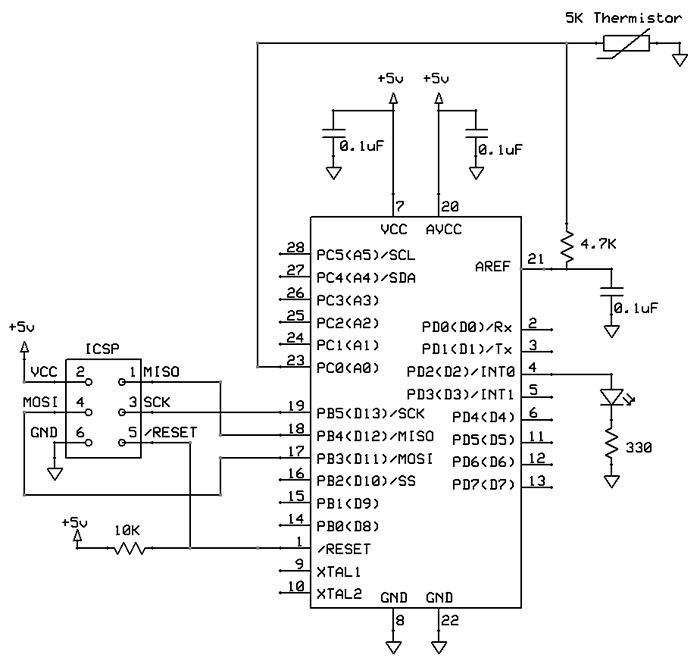
Using a "bare bones" board saves quite a bit of power.


Bare-bones board.

Sketch A above only draws 15.15 mA, a saving of 34.85 mA just by not using the development board. This would be accounted for by the fact that the development board has on it:


  • Voltage regulators (for +5V and +3.3V)
  • A USB interface chip (for the USB port)
  • A "power" LED


Sketch B above only draws 360 µA (0.360 mA) which is a LOT less. Still, you would expect about 31 mA less than the figure above for the Uno, so that sounds about right.

Also, with low power consumption I can put the multimeter on the "microamps" range which is more sensitive.

The initial outcome is that, to save power, forget about using a development board. Further savings (like reducing clock speed) would be overshadowed by the huge overhead of the voltage regulator and USB interface chip.

So from now on I'll experiment with the "bare bones" board. However it can still be programmed using the normal Arduino IDE (Integrated Development Environment). In my case I am using the USBtinyISP programming gadget, which you can get from here for around $US 22.

http://www.ladyada.net/make/usbtinyisp/

To program the board I changed a line in the Arduino preferences.txt file, as follows:


upload.using=usbtinyisp


The "bare bones" board I am playing with is from "Evil Mad Science" for around $US 13 for the board, processor chip, a ZIF (zero insertion force) socket, a 6-pin programming header, and a couple of other things:

http://evilmadscience.com/productsmenu/tinykitlist/230


The "Evil Mad Scientist" board. This particular one does not have the ZIF socket.

Different sleep modes


Let's substitute the various sleep modes in this line:


  set_sleep_mode (SLEEP_MODE_PWR_DOWN);  


Sleep modes and power consumption:


  • SLEEP_MODE_IDLE: 15 mA
  • SLEEP_MODE_ADC: 6.5 mA
  • SLEEP_MODE_PWR_SAVE: 1.62 mA
  • SLEEP_MODE_EXT_STANDBY: 1.62 mA
  • SLEEP_MODE_STANDBY : 0.84 mA
  • SLEEP_MODE_PWR_DOWN : 0.36 mA


Power-save mode lets you keep Timer 2 running (providing clocked from an external source).

Stand-by mode is similar to power-down mode, except that the oscillator is kept running. This lets it wake up faster.

Note: In IDLE mode, the clocks are running. This means that (unless you disable it) the normal Timer 0 clock used to count millis() will be running, and thus you will wake up approximately every millisecond.


Brown-out disable


Another power saving can be made by disabling the brown-out detection. To detect low voltages the processor must generate a voltage source for comparison purposes. You can change the "extended fuse" (efuse) by using AVRdude, like this:


avrdude -c usbtiny -p m328p -U efuse:w:0x07:m


In SLEEP_MODE_PWR_DOWN mode, with brown-out disabled, the power went down from 360 µA to 335 µA, a saving of 25 µA.

Another way of turning off brown-out detection is to temporarily disable it like this:

Sketch C


#include <avr/sleep.h>

void setup () 
{
  set_sleep_mode (SLEEP_MODE_PWR_DOWN);  
  noInterrupts ();           // timed sequence follows
  sleep_enable();
 
  // turn off brown-out enable in software
  MCUCR = bit (BODS) | bit (BODSE);  // turn on brown-out enable select
  MCUCR = bit (BODS);        // this must be done within 4 clock cycles of above
  interrupts ();             // guarantees next instruction executed
  sleep_cpu ();              // sleep within 3 clock cycles of above
}  // end of setup

void loop () { }


Note that this is a timed sequence. You must do sleep_cpu() directly after the bit manipulation or the brown-out disable is cancelled.

Turn off ADC (analog to digital conversion)


Next thing we can do turn off the ADC subsystem by adding this line:


  // disable ADC
  ADCSRA = 0;  


With that there the power consumption drops a large amount, down from 335 µA to 0.355 µA! (that is, 355 nA)


Configuring pins as inputs/outputs


Let's experiment with configuring the pins in various ways ...

Sketch D


#include <avr/sleep.h>

void setup () 
{

  for (byte i = 0; i <= A5; i++)
    {
    pinMode (i, OUTPUT);    // changed as per below
    digitalWrite (i, LOW);  //     ditto
    }
    
  // disable ADC
  ADCSRA = 0;  
  
  set_sleep_mode (SLEEP_MODE_PWR_DOWN);  
  noInterrupts ();           // timed sequence follows
  sleep_enable();
 
  // turn off brown-out enable in software
  MCUCR = bit (BODS) | bit (BODSE);
  MCUCR = bit (BODS); 
  interrupts ();             // guarantees next instruction executed
  sleep_cpu ();              // sleep within 3 clock cycles of above

}  // end of setup

void loop () { }


Testing in SLEEP_MODE_PWR_DOWN:


  • All pins as outputs, and LOW: 0.35 µA (same as before).

  • All pins as outputs, and HIGH: 1.86 µA.

  • All pins as inputs, and LOW (in other words, internal pull-ups disabled): 0.35 µA (same as before).

  • All pins as inputs, and HIGH (in other words, internal pull-ups enabled): 1.25 µA.


Note: This was tested with nothing connected to the pins. Obviously if you have an LED or something like that on an output pin, you will draw more current.


Power Reduction Register (PRR)


The next thing to experiment with is the Power Reduction Register (PRR). This lets you "turn off" various things inside the processor.

The various bits in this register turn off internal devices, as follows:


  • Bit 7 - PRTWI: Power Reduction TWI
  • Bit 6 - PRTIM2: Power Reduction Timer/Counter2
  • Bit 5 - PRTIM0: Power Reduction Timer/Counter0
  • Bit 4 - Res: Reserved bit
  • Bit 3 - PRTIM1: Power Reduction Timer/Counter1
  • Bit 2 - PRSPI: Power Reduction Serial Peripheral Interface
  • Bit 1 - PRUSART0: Power Reduction USART0
  • Bit 0 - PRADC: Power Reduction ADC


Tip:
The macros power_all_disable() and power_all_enable() modify the PRR register as appropriate for different processors.


Sketch E


#include <avr/sleep.h>
#include <avr/power.h>

void setup () 
{

  // disable ADC
  ADCSRA = 0;  

  // turn off various modules
  power_all_disable ();
  
  set_sleep_mode (SLEEP_MODE_IDLE);  
  noInterrupts ();           // timed sequence follows
  sleep_enable();
 
  // turn off brown-out enable in software
  MCUCR = bit (BODS) | bit (BODSE);
  MCUCR = bit (BODS); 
  interrupts ();             // guarantees next instruction executed
  sleep_cpu ();              // sleep within 3 clock cycles of above    
}  // end of setup

void loop () { }


Important note! You must use the PRR after setting ADCSRA to zero, otherwise the ADC is "frozen" in an active state.

Sketch F


#include <avr/power.h>

void setup () 
{
  power_all_disable();  // turn off all modules
}  // end of setup

void loop () { }


Sketch G


#include <avr/power.h>

void setup () 
{
  ADCSRA = 0;  // disable ADC
  power_all_disable ();   // turn off all modules
}  // end of setup

void loop () { }


According to the datasheet the PRR only applies in active (non-sleep) and idle modes. In other modes, those modules are already turned off.

Sleep modes and power consumption with PRR = 0xFF:


  • SLEEP_MODE_IDLE (Sketch E): 7.4 mA (was 15 mA)
  • Not sleeping (Sketch F): 14 mA (was 16.1 mA)
  • Not sleeping, no ADC (Sketch G): 13.6 mA (was 16.1 mA)


Turning on or off selected modules

Various macros (they vary by processor) let you power on or off individual modules:

Enabling:


  • power_adc_enable(); // ADC converter
  • power_spi_enable(); // SPI
  • power_usart0_enable(); // Serial (USART)
  • power_timer0_enable(); // Timer 0
  • power_timer1_enable(); // Timer 1
  • power_timer2_enable(); // Timer 2
  • power_twi_enable(); // TWI (I2C)


Disabling:


  • power_adc_disable(); // ADC converter
  • power_spi_disable(); // SPI
  • power_usart0_disable();// Serial (USART)
  • power_timer0_disable();// Timer 0
  • power_timer1_disable();// Timer 1
  • power_timer2_disable();// Timer 2
  • power_twi_disable(); // TWI (I2C)


Using the internal clock


By changing the fuse bits the processor can run on its 8 MHz internal clock. Running Sketch A above, with lfuse set to 0xE2, the board consumed 11.05 mA (compared to 15.15 mA using the crystal).

You can change the clock like this:


avrdude -c usbtiny -p m328p -U lfuse:w:0xE2:m


Another way of changing the clock speed is to enable the "divide clock by 8" fuse bit. So this gives you various other options, like a 16 MHz crystal divided by 8 giving 2 MHz, or the internal 8 MHz oscillator, divided by 8, giving 1 Mhz.

You can also run the processor on a low-power 128 KHz internal clock. Running Sketch A above, with lfuse set to 0xE3, the board consumed 6 mA (compared to 16.1 mA using the crystal).

Note that using the slower clock doesn't really help in sleep mode, because the clock is stopped anyway.

Warning: Once the clock is set to 128 KHz, you will have trouble programming the board. You need to add -B250 to the AVRdude command line. For example, to put the clock back to using the crystal:


avrdude -c usbtiny -p m328p -U lfuse:w:0xFF:m -B250


There is a fuse calculator for boards here:

http://www.engbedded.com/fusecalc

Another warning: Pay close attention to the fuse bit settings. If you get them wrong you can "brick" your processor. It can be recovered with a high-voltage programmer like the AVR Dragon, if you have one handy. In particular you don't want to turn off SPIEN (Enable Serial programming and Data Downloading). Nor do you want to turn on RSTDISBL (External reset disable).

Summary of clock speeds and current


lfuse   Speed    Current
0xFF    16 MHz    15.15 mA
0xE2     8 MHz    11.05 mA
0x7F     2 MHz     7.21 mA
0x62     1 MHz     6.77 mA
0xE3   128 KHz     6.00 mA 


Another point is that running from a slower clock means, that if you sleep and wake, you are awake for longer (potentially 16 times as long if you cut a 16 MHz processor down to 1 MHz). So if you consume more power when awake, and are awake for much longer, then that can outweigh the savings from running at slower speeds.

Waking from sleep with a timer


Well, this sleeping as all very well, but a processor that stays asleep isn't particularly useful. Although, I have seen an example of that: the TV Begone remote control. What that does is send out some codes (to turn TVs off) and then goes to sleep permanently. The "activate" button on the gadget is the reset button. When you press that it does its stuff again.

Meanwhile this sketch below shows how you can use the watchdog timer to sleep for 8 seconds (the maximum you can set up a watchdog for) and then flash the LED 10 times, and go back to sleep. Whilst asleep it uses about 6.54 µA of current, so presumably the watchdog timer has a bit of an overhead (like, 6.2 µA).

Sketch H


#include <avr/sleep.h>
#include <avr/wdt.h>

const byte LED = 9;

void flash ()
  {
  pinMode (LED, OUTPUT);
  for (byte i = 0; i < 10; i++)
    {
    digitalWrite (LED, HIGH);
    delay (50);
    digitalWrite (LED, LOW);
    delay (50);
    }
    
  pinMode (LED, INPUT);
    
  }  // end of flash
  
// watchdog interrupt
ISR (WDT_vect) 
{
   wdt_disable();  // disable watchdog
}  // end of WDT_vect
 
void setup () { }

void loop () 
{
 
  flash ();
  
  // disable ADC
  ADCSRA = 0;  

  // clear various "reset" flags
  MCUSR = 0;     
  // allow changes, disable reset
  WDTCSR = bit (WDCE) | bit (WDE);
  // set interrupt mode and an interval 
  WDTCSR = bit (WDIE) | bit (WDP3) | bit (WDP0);    // set WDIE, and 8 seconds delay
  wdt_reset();  // pat the dog
  
  set_sleep_mode (SLEEP_MODE_PWR_DOWN);  
  noInterrupts ();           // timed sequence follows
  sleep_enable();
 
  // turn off brown-out enable in software
  MCUCR = bit (BODS) | bit (BODSE);
  MCUCR = bit (BODS); 
  interrupts ();             // guarantees next instruction executed
  sleep_cpu ();  
  
  // cancel sleep as a precaution
  sleep_disable();
  
  } // end of loop


This slightly different example shows how you can flash an LED once a second (approximately) and then go to sleep for the rest of the time:

Sketch I


#include <avr/sleep.h>
#include <avr/wdt.h>

const byte LED = 9;
  
// watchdog interrupt
ISR (WDT_vect) 
{
   wdt_disable();  // disable watchdog
}  // end of WDT_vect
 
void setup () { }

void loop () 
{
 
  pinMode (LED, OUTPUT);
  digitalWrite (LED, HIGH);
  delay (50);
  digitalWrite (LED, LOW);
  pinMode (LED, INPUT);
  
  // disable ADC
  ADCSRA = 0;  

  // clear various "reset" flags
  MCUSR = 0;     
  // allow changes, disable reset
  WDTCSR = bit (WDCE) | bit (WDE);
  // set interrupt mode and an interval 
  WDTCSR = bit (WDIE) | bit (WDP2) | bit (WDP1);    // set WDIE, and 1 second delay
  wdt_reset();  // pat the dog
  
  set_sleep_mode (SLEEP_MODE_PWR_DOWN);  
  noInterrupts ();           // timed sequence follows
  sleep_enable();
 
  // turn off brown-out enable in software
  MCUCR = bit (BODS) | bit (BODSE);
  MCUCR = bit (BODS); 
  interrupts ();             // guarantees next instruction executed
  sleep_cpu ();  
  
  // cancel sleep as a precaution
  sleep_disable();
  
  } // end of loop


To save you looking up the various combinations of wake-up time here is the table from the datasheet for the Atmega328:


Basically you set some of the bits named WDP0 through to WDP3 as per the table, to get different times. Note that the smallest is 16 mS and the longest is 8 S.

You could arrange longer sleep times by having a "counting" loop and sleep/wake/sleep/wake for x times.

Note that the watchdog timer is independent of the clock speed of the processor, so an 8-second watchdog timer is still that, regardless of what speed you are clocking the processor at.

Warning about wake-up times

Various fuse settings make a big difference to the wake-up time. Some wake-up times are quite long (eg. 65 mS) because they are designed to allow the crystal clock to settle. If you are trying to save power, taking 65 mS to wake up, add 1 to a counter, and go back to sleep, is a lot. You would want to look at a "wake-up" fuse setting that is appropriate for the type of clock source you are using.

Note that if you disable brown-out detection in software rather than by changing the fuse settings then it takes around 60 µs longer to wake up, as mentioned in the datasheet:

Quote:

If BOD is disabled in software, the BOD function is turned off immediately after entering the sleep mode. Upon wake-up from sleep, BOD is automatically enabled again.
...
When the BOD has been disabled, the wake-up time from sleep mode will be approximately 60 μs to ensure that the BOD is working correctly before the MCU continues executing code.


For a fast wake-up (which means you get on with what you want to do more quickly) disable brown-out detection by altering the fuses. That's assuming you want to disable brown-out detection.


Waking from sleep with a signal


Another way of waking from sleep is to detect a logic level change on an interrupt pin (D2 or D3 on the Arduino). These are processor pins 4 and 5 on the actual Atmega328 chip.

Any interrupt will wake the processor, as this sketch demonstrates. When asleep it uses 0.15 µA of current.

Sketch J


#include <avr/sleep.h>

const byte LED = 9;
  
void wake ()
{
  // cancel sleep as a precaution
  sleep_disable();
  // precautionary while we do other stuff
  detachInterrupt (0);
}  // end of wake

void setup () 
  {
  digitalWrite (2, HIGH);  // enable pull-up
  }  // end of setup

void loop () 
{
 
  pinMode (LED, OUTPUT);
  digitalWrite (LED, HIGH);
  delay (50);
  digitalWrite (LED, LOW);
  delay (50);
  pinMode (LED, INPUT);
  
  // disable ADC
  ADCSRA = 0;  
  
  set_sleep_mode (SLEEP_MODE_PWR_DOWN);  
  sleep_enable();

  // Do not interrupt before we go to sleep, or the
  // ISR will detach interrupts and we won't wake.
  noInterrupts ();
  
  // will be called when pin D2 goes low  
  attachInterrupt (0, wake, FALLING);
  EIFR = bit (INTF0);  // clear flag for interrupt 0
 
  // turn off brown-out enable in software
  // BODS must be set to one and BODSE must be set to zero within four clock cycles
  MCUCR = bit (BODS) | bit (BODSE);
  // The BODS bit is automatically cleared after three clock cycles
  MCUCR = bit (BODS); 
  
  // We are guaranteed that the sleep_cpu call will be done
  // as the processor executes the next instruction after
  // interrupts are turned on.
  interrupts ();  // one cycle
  sleep_cpu ();   // one cycle

  } // end of loop


You could combine both methods. That is, have a watchdog, and a logic level change interrupt.


Other power-saving techniques


  • If you must use a voltage regulator, try to find one with a low quiescent current. For example the LM7805 itself consumes around 5 mA, so there isn't much use putting a lot of effort into saving the last microamp if your voltage regulator consumes 5 mA non-stop. For example, if you use 3 x 1.5V batteries, you should get around 4.5V which would be enough to power a processor without needing a voltage regulator.

  • Go easy on "power" LEDs. LEDs can use quite a bit of current (say, 10 mA). If possible just flash one briefly rather than have it on all the time, or use a low-power LED. Experimentation shows that flashing an LED for 5 mS to 10 mS is quite noticeable. So, one 10 mS flash per second is only an overhead of one percent.

  • If you have an external peripheral (eg. a clock chip) you could "power" it from a digital pin, and then turn it off when not required. For example, the DS1307 clock chip only uses 1.5 mA when active, so that could be powered by a digital pin.

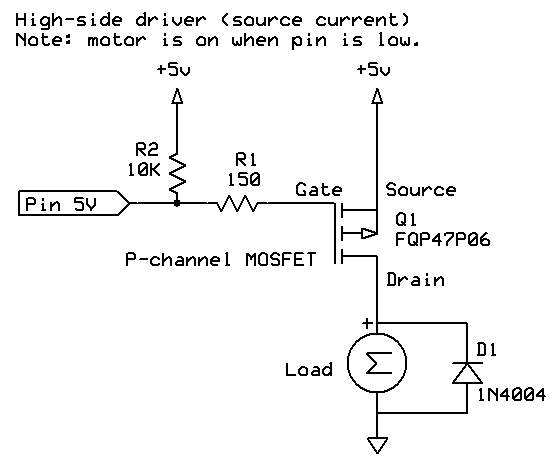
  • For higher power devices you could use a MOSFET transistor to turn the current on/off to it as required.

  • Run the processor on a lower voltage (eg. 3.3V). For example Sketch H above only uses 4.6 µA when asleep, running on 3.3V, compared to 6.4 µA at 5V.

  • Sleep the processor as much as possible, even if that means sleeping every second. For example I have a GPS clock that sleeps every second, waking just long enough to "tick" the hand around. Every day or so it wakes up for longer, powers up a GPS module, and resynchronizes its internal time with the GPS time.


Summary of power savings


Figures are the amount saved by each method, in milliamps:


Bypassing the "power plug"           8.4
Using a "bare bones" board          30.5
Power-down sleep mode               15.7
Use internal clock at 128 KHz       10.1
Use Power Reduction Register (PRR)   7.6
Use internal clock at 8 MHz          5.4


In sleep mode, saving in microamps:


Turn off ADC converter               334
Disable brown-out detection           25
Set all pins to input and low          2


Power budgeting


You can work out how long your project will last on a battery by doing a "power budget". That is, work out the average amount of power consumed. For example, if you use 5 mA for 1% of the time that would be an average of 0.05 mA (assuming that for the remaining 99% of the time you used a tiny amount like 0.35 µA).

Some typical battery capacities might be, in mA hours:


CR1212           18
CR1620           68
CR2032          210
NiMH AAA        900
Alkaline AAA   1250
NiMH AA        2400
Alkaline AA    2890
Li-Ion *       4400


* Li-Ion batteries come in a wide variety of sizes, this is just an example.

So for example, running from AAA batteries, drawing an average of 0.05 mA, the device could run for 1250 / 0.05 = 25000 hours (1041 days, or 33 months).

Also batteries have a self-discharge rate, so you would need to factor that in. The battery may self-discharge faster than your circuit discharges it! See the post further down for a discussion about self-discharge rates.


Also see this page about interrupts:

http://gammon.com.au/interrupts


[EDIT]

Confirmed low-current readings with Dave Jones' uCurrent device:


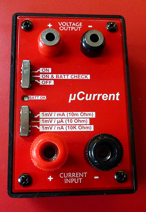
Available for $AUD 49.95 (at present) from:

http://www.eevblog.com/shop/

Warning! It tends to sell out very quickly.

- Nick Gammon

www.gammon.com.au, www.mushclient.com
[Go to top] top

Posted by Nick Gammon   Australia  (22,975 posts)  [Biography] bio   Forum Administrator
Date Reply #1 on Fri 13 Jan 2012 11:01 PM (UTC)

Amended on Sat 23 Aug 2014 05:28 AM (UTC) by Nick Gammon

Message
Waking I2C slave from sleep


Below is an example of waking an I2C slave from sleep. First, a master which wants to talk to the slave:

Master


// I2C master

#include <Wire.h>

const byte SLAVE_ADDRESS = 42;

void setup() 
{
  Wire.begin ();
}  // end of setup

void loop() 
{
byte status;

  for (byte i = 1; i <= 10; i++)
    {  
    // wake slave up
    Wire.beginTransmission (SLAVE_ADDRESS);
    Wire.endTransmission ();
    
    delay (5);  // give it time to recover
    
    Wire.beginTransmission (SLAVE_ADDRESS);
    Wire.send (i);
    status = Wire.endTransmission ();  // 0 is OK
    delay (5000);
    } // end of for loop
}  // end of loop


The above master sends a number (from 1 to 10) every 5 seconds to a slave at address 42.

To give the slave time to react to waking up it first does a beginTransmission/endTransmission pair, which just causes the slave to wake. Then it waits briefly for the slave's clock to stabilize, and then sends the "real" message.


Slave


// I2C slave that sleeps

#include <Wire.h>
#include <avr/sleep.h>

const byte MY_ADDRESS = 42;
const byte AWAKE_LED = 8;
const byte GREEN_LED = 9;
const unsigned long WAIT_TIME = 500;

volatile byte flashes;
volatile unsigned long counter;

void setup() 
{
  pinMode (GREEN_LED, OUTPUT);
  pinMode (AWAKE_LED, OUTPUT);
  digitalWrite (AWAKE_LED, HIGH);
  Wire.begin (MY_ADDRESS);
  Wire.onReceive (receiveEvent);
  
} // end of setup

void loop() 
{
  if (++counter >= WAIT_TIME)
    {
    byte old_ADCSRA = ADCSRA;
    // disable ADC
    ADCSRA = 0;  
    set_sleep_mode (SLEEP_MODE_PWR_DOWN);  
    sleep_enable();
    digitalWrite (AWAKE_LED, LOW);
    sleep_cpu ();      
    digitalWrite (AWAKE_LED, HIGH);
    sleep_disable();
    counter = 0;
    ADCSRA = old_ADCSRA;
    
    // release TWI bus
    TWCR = bit(TWEN) | bit(TWIE) | bit(TWEA) | bit(TWINT);
    
    // turn it back on again
    Wire.begin (MY_ADDRESS);
    }  // end of time to sleep
  
  
  // flash LED x times where x was the number received from the master
  for (byte i = 0; i < flashes; i++)
    {
    digitalWrite (GREEN_LED, HIGH);
    delay (200);  
    digitalWrite (GREEN_LED, LOW);
    delay (200);  
    }
    
   flashes = 0;
   
}  // end of loop

void receiveEvent (int howMany)
 {
  counter = 0;
  
  flashes = 0;
  if (Wire.available () > 0)
    flashes = Wire.receive ();
  
  // flush remaining bytes
  while (Wire.available () > 0)
    Wire.receive ();
}  // end of receiveEvent


The slave goes to sleep after WAIT_TIME trips around the main loop. This delay allows the master time to wake it, and then, whilst awake, send it the "real" message.

It also appeared to be necessary to reinitialize the I2C bus after being woken because it didn't appear to be in a stable state otherwise.

I have a couple of LEDs there - the "green" one on pin D9 flashes the appropriate number of times. Also there is an "awake" LED which helps debug whether the processor is asleep or awake.

Whilst asleep, I measured about 0.071 mA (71 µA) of current drawn.

- Nick Gammon

www.gammon.com.au, www.mushclient.com
[Go to top] top

Posted by Nick Gammon   Australia  (22,975 posts)  [Biography] bio   Forum Administrator
Date Reply #2 on Wed 25 Jan 2012 05:08 AM (UTC)

Amended on Sat 26 Sep 2015 08:38 PM (UTC) by Nick Gammon

Message
More savings with lower voltages


Running sketch A above, namely:


void setup () {}
void loop () {}


And setting the processor to use the internal 8 MHz clock, like this:


avrdude -c usbtiny -p m328p -U lfuse:w:0xE2:m


Let's compare the current drawn at various voltages:


  • 5.0V : 11.67 mA
  • 4.5V : 7.74 mA
  • 4.0V : 5.60 mA
  • 3.5V : 4.10 mA
  • 3.3V : 3.70 mA *
  • 3.0V : 3.30 mA
  • 2.8V : 3.00 mA
  • 2.5V : 2.70 mA
  • 2.4V : 2.50 mA
  • 2.3V : 2.40 mA
  • 2.2V : 2.30 mA
  • 2.1V : 2.10 mA


Clearly substantial power savings can be made by simply running at a lower voltage, if that is practical. And that is running at 8 MHz and without sleeping!

* A lot of devices are manufactured today to run at 3.3V, so interfacing with them at that voltage should not be a problem.

[EDIT] Further tests show that the low currents reported for 3.0V and below were anomalous because the chip was not in fact running. (23 December 2012)

[EDIT] Further testing again showed this was because brown-out detection was enabled at 2.7V. With that disabled, you can get down to around 2.1V at 8 MHz although 2.4V is the minimum recommended in the datasheet.


Now if we drop the processor speed down to 128 KHz, like this:


avrdude -c usbtiny -p m328p -U lfuse:w:0xE3:m


Then we get:


  • 2.5V : 0.19 mA
  • 1.8V : 0.14 mA


Of course you may not want to run at those voltages, or speeds. But for something like monitoring a water tank level you can see that quite modest power consumptions can be achieved, even without sleeping. Of course, if you sleep as well you can save even more.

How many volts per Megaherz?


This chart from the Atmega328 datasheet shows the number of volts required for each speed:


Translated into formulae we see that:


  • Below 1.8V - cannot operate
  • Below 4 MHz - use at least 1.8V
  • Between 4 MHz and 10 MHz you require: Volts = 1.8 + ((M - 4) * 0.15)
    (Where M is Megaherz)
  • Between 10 Mhz and 20 MHz you require: Volts = 2.7 + ((M - 10) * 0.18)
    (Where M is Megaherz)
  • You can supply an absolute maximum of 5.5V


Re-arranging the formula to calculate a maximum speed for a given voltage:


  • From 1.8V to 2.7V: M = 4 + ((V - 1.8) / 0.15)
  • From 2.7V to 4.5V: M = 10 + ((V - 2.7) / 0.18)


For example, if you are planning to run at 2V:


MHz = 4 + ((2 - 1.8) / 0.15)
    = 4 + (0.2 / 0.15)
    = 4 + 1.33
    = 5.33


So we could run at just over 5 MHz at 2V.

Summary of volts per MHz


To summarize the voltages required for each MHz of frequency, from the above formulae:


MHz  Volts
 4    1.80
 5    1.95
 6    2.10
 7    2.25
 8    2.40
 9    2.55
10    2.70
11    2.88
12    3.06
13    3.24
14    3.42
15    3.60
16    3.78
17    3.96
18    4.14
19    4.32
20    4.50


Battery self-discharge rates


A discussion of power saving techniques isn't really complete without considering the self-discharge rates of various types of batteries. There isn't much point in saving a micro-amp here and there if the battery is self-discharging at the rate of 500 µA!

Based on various pieces of research, I have put together a guide for the rate at which various types of batteries self-discharge, and therefore what the "equivalent" current is:


Type        Capacity mAH  Discharge %/month   Self discharge (µA)

CR1212            18              1                  0.250
CR1620            68              1                  0.950
CR2032           210              1                  3
NiCD AAA         350             20                 98
NiMH AAA         900             30                375
NiCd AA         1000             20                270
Alkaline AAA    1250              2                 35
NiMH AA         2400             30               1000
Alkaline AA     2890              2                 80
Li-Ion          4400             10                600


All figures are approximate and intended as a guide only. Different batteries have different capacities, and self-discharge rates are not flat (that is, they tend to self-discharge faster at the start). Also self-discharge rates are influenced by temperature.

You can see that NiMH batteries in particular discharge very quickly, so even just leaving one in a box is equivalent to connecting it up to circuit which draws 1 mA!

On the other hand, lithium (button) batteries discharge quite slowly (at 250 nA), so saving a microamp in your application is worthwhile.

Formula for self-discharge rates


Batteries are often quoted with a self-discharge rate of x% per month.

So, for (say) a battery with 1250 mAH of capacity, and a 2% self-discharge rate, per month, it follows that at the end of one month, we will have lost 2 / 100 * 1250 mAH of capacity. That is, 25 mAH less are available. It further follows that we would have lost (x / 100) / (24 * 30) capacity in one hour (24 hours in a day, 30 days in a month, average). Thus we have lost 25 / (24 * 30) = 0.03472 mAH capacity in one hour.

To lose 0.03472 mAH capacity over one hour we would have to have had a current consumption of 0.03472 mA for that hour. Thus the self-discharge rate is effectively the same as using 34.72 µA continuously.

So:


equivalent_current_mA = (percent_monthly_discharge_rate / 100) * capacity_maH / (24 * 30) 


Detecting low voltage


All this power saving is well and good, but eventually our battery will run down, and we need to detect that so we can flash a "low battery" LED, sound a beeper, or something.

One reasonably useful way of doing that is to let the processor work out its own Vcc (power) voltage. To do this, we can use the function getBandgap, which finds the voltage of the Vcc line by using the ADC converter to compare the Vcc line to the internal 1.1 reference voltage.

An example sketch which demonstrates the technique:


void setup(void)
  {
  Serial.begin(115200);
  }
    
void loop(void)
  {
  Serial.println (getBandgap ());
  delay(1000);
  }

const long InternalReferenceVoltage = 1062;  // Adjust this value to your board's specific internal BG voltage
 
// Code courtesy of "Coding Badly" and "Retrolefty" from the Arduino forum
// results are Vcc * 100
// So for example, 5V would be 500.
int getBandgap () 
  {
  // REFS0 : Selects AVcc external reference
  // MUX3 MUX2 MUX1 : Selects 1.1V (VBG)  
   ADMUX = bit (REFS0) | bit (MUX3) | bit (MUX2) | bit (MUX1);
   ADCSRA |= bit( ADSC );  // start conversion
   while (ADCSRA & bit (ADSC))
     { }  // wait for conversion to complete
   int results = (((InternalReferenceVoltage * 1024) / ADC) + 5) / 10; 
   return results;
  } // end of getBandgap


If you try this out you should see some numbers scroll by, close to 500 (if you are using 5V power source). There will be an error factor of a few percent, but it should be close enough that you can use it to predict when the battery is getting low.

To get a more accurate result, you need to find the internal reference voltage. To do that, run this sketch:


// Find internal 1.1 reference voltage on AREF pin
void setup ()
{
  ADMUX = bit (REFS0) | bit (REFS1);
}
void loop () { }


Or, more simply:


// Find internal 1.1 reference voltage on AREF pin
void setup ()
{
  analogReference (INTERNAL);
  analogRead (A0);  // force voltage reference to be turned on
}
void loop () { }


Then use a voltmeter to measure the voltage on the AREF pin of the processor. Multiply that by 1000 and use it as the InternalReferenceVoltage variable above. For example, I got 1.062 volts when I tried it.

If you are deploying your sketch on multiple processors you might store the internal reference voltage in EEPROM, for each processor, so the sketch can consult that to find the exact figure to use when calculating the voltage.


Warning about low voltage


The next issue is, how do we tell our users that the battery needs replacing? Once we know the battery voltage is low, we need to somehow communicate that fact. Of course, if we have some sort of communication system (eg. radio, Ethernet) we can simply transmit a "low battery" message.

Failing that, a warning LED might do the trick. The problem is that turning on an LED is likely to drain the battery even faster, so we need to do it with caution.

Experiments with "high-power" (8000 mcd) LEDs show that, even pulsed at only 1 mS per second, they are quite noticeable, at least if you are looking straight at them.

So a function like this could make a flashing "warning" LED:


void lowBatteryWarning () 
  {
  digitalWrite (LED, HIGH);  
  delay (1);       // mS        
  digitalWrite (LED, LOW);    
  delay (999);             
  }


Since this has a duty cycle of 1/1000 of a second, then the 20 mA current drawn is divided by 1000, so on average it is drawing 20 µA. In my test I had a 100 ohm resistor in series with the LED. In fact even an "ordinary" red LED, with the 100 ohm resistor, and the same blink rate, was quite visible.

Battery life calculator


You may find this battery life calculator useful.

- Nick Gammon

www.gammon.com.au, www.mushclient.com
[Go to top] top

Posted by Nick Gammon   Australia  (22,975 posts)  [Biography] bio   Forum Administrator
Date Reply #3 on Sat 28 Jan 2012 02:08 AM (UTC)

Amended on Sun 05 Apr 2015 11:37 PM (UTC) by Nick Gammon

Message
Powering off external devices


Another thing you can do to save power is "power off" external chips (such as clock chips) when they aren't needed.

As an example, say you need to know the time (because you are logging temperatures inside your shed, for instance). But to leave the Real Time Clock (RTC) chip running all the time might use a few hundred microamps, if not more.

To save that current, power the clock from a spare digital pin (eg. D8) and just set the pin to output, and high (+5V) when required. Example circuit:


The 220 ohm resistor is to stop too much current flowing through the output pin to charge the 0.1 uF decoupling capacitor. Since we don't want much more than 20 mA drawn from the pin, the value R = E/I, namely 5 / 0.020, giving 250 ohms. In fact 220 ohms (the nearest standard resistor value) would allow a maximum of 22.7 mA, which is acceptable for an output pin.

An example sketch:


#include <Wire.h>
#include "RTClib.h"

#include <avr/sleep.h>
#include <avr/wdt.h>

RTC_DS1307 RTC;

#define CLOCK_POWER 8

// watchdog interrupt
ISR (WDT_vect) 
{
  wdt_disable();  // disable watchdog
}

void myWatchdogEnable() 
{
  // clear various "reset" flags
  MCUSR = 0;     
  // allow changes, disable reset
  WDTCSR = bit (WDCE) | bit (WDE);
  // set interrupt mode and an interval 
  WDTCSR = bit (WDIE) | bit (WDP3) | bit (WDP0);    // set WDIE, and 8 seconds delay
  wdt_reset();  // pat the dog

  // disable ADC
  ADCSRA = 0;  

  // ready to sleep
  set_sleep_mode (SLEEP_MODE_PWR_DOWN);  
  sleep_enable();

  // turn off brown-out enable in software
  MCUCR = bit (BODS) | bit (BODSE);
  MCUCR = bit (BODS); 
  sleep_cpu ();  

  // cancel sleep as a precaution
  sleep_disable();
} 

void setup()
{
  RTC.begin();  // activate clock (doesn't do much)
}  // end of setup

void loop()
{

  // power up clock chip
  digitalWrite (CLOCK_POWER, HIGH);
  pinMode (CLOCK_POWER, OUTPUT);

  // activate I2C
  Wire.begin();

  // find the time  
  DateTime now = RTC.now();

  // time now available in now.hour(), now.minute() etc.

  // finished with clock
  pinMode (CLOCK_POWER, INPUT);  
  digitalWrite (CLOCK_POWER, LOW); 

  // turn off I2C
  TWCR &= ~(bit(TWEN) | bit(TWIE) | bit(TWEA));

  // turn off I2C pull-ups
  digitalWrite (A4, LOW);
  digitalWrite (A5, LOW);


  // -------- do something here if required by the time of day


  // sleep for a total of 64 seconds (8 x 8)
  for (int i = 0; i < 8; i++)
    myWatchdogEnable (); 

}  // end of loop


A couple of tricky parts:


  • We make the pin high before switching it to output, to save forcing the capacitor low
  • The RTC chip is actually "alive" all the time from its battery backup, it just is not allowed to use I2C without external power. So we don't have to wait long before we use it.
  • Once finished we set the pin to input first, and then to low, again to save draining the capacitor
  • We turn off the I2C hardware
  • We turn off the I2C pull-ups to save power


Then a loop of 8 lots of 8-second watchdog timer sleeps gives us about a minute's delay. Of course we could make that longer. Then we can check the time from the clock to see if it is time to do anything.

The measured current drain during that test was 6.4 µA almost all of the time, with a current drain of 22.8 mA for 1 mS (while the clock was being read).

This technique requires that the device you are powering from a digital pin does not draw more than the pin can supply (ie. 20 mA). If it required more you would need to turn on a MOSFET transistor which in turn could power on the device.

[EDIT] As pointed out on the Arduino forum, the voltage drop over the 220 ohm resistor is going to make this system not work for devices that draw much more than a milliamp or so. In the case of the DS1307, it draws around 1.5 mA when active, so over 220 ohms there would be a voltage drop from 5V of 0.33V, bringing it close to its lower operating voltage.

For devices that draw more current it is probably better to drive a suitable MOSFET to switch the power on and off ...


- Nick Gammon

www.gammon.com.au, www.mushclient.com
[Go to top] top

Posted by Nick Gammon   Australia  (22,975 posts)  [Biography] bio   Forum Administrator
Date Reply #4 on Sat 17 Nov 2012 10:59 PM (UTC)

Amended on Mon 24 Oct 2016 09:19 PM (UTC) by Nick Gammon

Message
Detecting key presses on a keypad whilst asleep


The sketch below illustrates how you can connect up a 16-key keypad to your processor, and then sleep until a key is pressed.

This uses the Keypad2 library (not sure where I got that) but the concept should be similar for all similar libraries.

The general idea is that, before sleeping, the sketch sets all the rows to HIGH (pull-up) and all columns to LOW (output). Now, if no button is pressed all the rows will be high (because of the pull-up). Then if a button is pressed the row will go LOW, and cause a pin change. The pin-change interrupt fires, waking the processor.

The sketch then reconfigures the rows and columns back to how they were in the keypad library, and calls keypad.getKey () to find which key was pressed.


// Wake from deep sleep with a keypress demonstration

// Author: Nick Gammon
// Date: 18th November 2012

#include <Keypad2.h>
#include <avr/sleep.h>
#include <avr/power.h>

const byte ROWS = 4;
const byte COLS = 4; 

char keys[ROWS][COLS] = 
  {
    {'1', '2', '3', 'A'},
    {'4', '5', '6', 'B'},
    {'7', '8', '9', 'C'},
    {'*', '0', '#', 'D'},
  };

byte rowPins[ROWS] = {6, 7, 8, 9}; //connect to the row pinouts of the keypad
byte colPins[COLS] = {2, 3, 4, 5}; //connect to the column pinouts of the keypad
  
// number of items in an array
#define NUMITEMS(arg) ((unsigned int) (sizeof (arg) / sizeof (arg [0])))

const byte ledPin = 13;

  // Create the Keypad
Keypad kpd = Keypad( makeKeymap(keys), rowPins, colPins, ROWS, COLS );

/*

Pin change interrupts.

Pin                  Mask / Flag / Enable

D0	  PCINT16 (PCMSK2 / PCIF2 / PCIE2)
D1	  PCINT17 (PCMSK2 / PCIF2 / PCIE2)
D2	  PCINT18 (PCMSK2 / PCIF2 / PCIE2)
D3	  PCINT19 (PCMSK2 / PCIF2 / PCIE2)
D4	  PCINT20 (PCMSK2 / PCIF2 / PCIE2)
D5	  PCINT21 (PCMSK2 / PCIF2 / PCIE2)
D6	  PCINT22 (PCMSK2 / PCIF2 / PCIE2)
D7	  PCINT23 (PCMSK2 / PCIF2 / PCIE2)
D8	  PCINT0 (PCMSK0 / PCIF0 / PCIE0)
D9	  PCINT1 (PCMSK0 / PCIF0 / PCIE0)
D10	  PCINT2 (PCMSK0 / PCIF0 / PCIE0)
D11	  PCINT3 (PCMSK0 / PCIF0 / PCIE0)
D12	  PCINT4 (PCMSK0 / PCIF0 / PCIE0)
D13	  PCINT5 (PCMSK0 / PCIF0 / PCIE0)
A0	  PCINT8 (PCMSK1 / PCIF1 / PCIE1)
A1	  PCINT9 (PCMSK1 / PCIF1 / PCIE1)
A2	  PCINT10 (PCMSK1 / PCIF1 / PCIE1)
A3	  PCINT11 (PCMSK1 / PCIF1 / PCIE1)
A4	  PCINT12 (PCMSK1 / PCIF1 / PCIE1)
A5	  PCINT13 (PCMSK1 / PCIF1 / PCIE1)

*/

// turn off interrupts until we are ready
ISR (PCINT0_vect)
  {
  PCICR = 0;  // cancel pin change interrupts
  } // end of ISR (PCINT0_vect)

ISR (PCINT1_vect)
  {
  PCICR = 0;  // cancel pin change interrupts
  } // end of ISR (PCINT1_vect)

ISR (PCINT2_vect)
  {
  PCICR = 0;  // cancel pin change interrupts
  } // end of ISR (PCINT2_vect)

void setup ()
  {
  pinMode (ledPin, OUTPUT);
  
  // pin change interrupt masks (see above list)
  PCMSK2 |= bit (PCINT22);   // pin 6
  PCMSK2 |= bit (PCINT23);   // pin 7
  PCMSK0 |= bit (PCINT0);    // pin 8
  PCMSK0 |= bit (PCINT1);    // pin 9

  }  // end of setup

// set pins as keypad library expects them
// or call: kpd.initializePins ();
//    however in the library I have that is a private method

void reconfigurePins ()
  {
  byte i;
  
  // go back to all pins as per the keypad library
  
  for (i = 0; i < NUMITEMS (colPins); i++)
    {
    pinMode (colPins [i], OUTPUT);
    digitalWrite (colPins [i], HIGH); 
    }  // end of for each column 

  for (i = 0; i < NUMITEMS (rowPins); i++)
    {
    pinMode (rowPins [i], INPUT_PULLUP);
    }   // end of for each row

  }  // end of reconfigurePins

void goToSleep ()
  {
  byte i;
   
  // set up to detect a keypress
  for (i = 0; i < NUMITEMS (colPins); i++)
    {
    pinMode (colPins [i], OUTPUT);
    digitalWrite (colPins [i], LOW);   // columns low
    }  // end of for each column

  for (i = 0; i < NUMITEMS (rowPins); i++)
    {
    pinMode (rowPins [i], INPUT_PULLUP);
    }  // end of for each row
    
   // now check no pins pressed (otherwise we wake on a key release)
   for (i = 0; i < NUMITEMS (rowPins); i++)
    {
    if (digitalRead (rowPins [i]) == LOW)
       {
       reconfigurePins ();
       return; 
       } // end of a pin pressed
    }  // end of for each row
  
  // overcome any debounce delays built into the keypad library
  delay (50);
  
  // at this point, pressing a key should connect the high in the row to the 
  // to the low in the column and trigger a pin change
  
  set_sleep_mode (SLEEP_MODE_PWR_DOWN);  
  sleep_enable();

  byte old_ADCSRA = ADCSRA;
  // disable ADC to save power
  ADCSRA = 0;  

  power_all_disable ();  // turn off various modules
   
  PCIFR  |= bit (PCIF0) | bit (PCIF1) | bit (PCIF2);   // clear any outstanding interrupts
  PCICR  |= bit (PCIE0) | bit (PCIE1) | bit (PCIE2);   // enable pin change interrupts
   
  // turn off brown-out enable in software
  MCUCR = bit (BODS) | bit (BODSE);
  MCUCR = bit (BODS); 
  sleep_cpu ();  
 
  // cancel sleep as a precaution
  sleep_disable();
  power_all_enable ();   // enable modules again
  ADCSRA = old_ADCSRA;   // re-enable ADC conversion
  
  // put keypad pins back how they are expected to be
  reconfigurePins ();
    
  }  // end of goToSleep
  
void loop () 
  {
   
   byte key =  kpd.getKey();
   if (!key)
     {
     // no key pressed? go to sleep
     goToSleep ();
     return;
     }

  // confirmation we woke - flash LED number of times
  // for the appropriate pin (eg. pin 1: one time) 
  for (byte i = 0; i < (key - '0'); i++)
    {
    digitalWrite (ledPin, HIGH);
    delay (500); 
    digitalWrite (ledPin, LOW);
    delay (500); 
    } // end of for loop
    
  } // end of loop


Power consumption

Tested on a "bare bones" board, when asleep the sketch used only 100 nA (0.1 µA) of power, even on a 5V supply, and a 16 MHz clock rate.

The sketch above just flashes LED 13 to prove it woke up, but in practice you would replace that code (at the end) to do something useful.

Applications

This general idea would be useful in situation where you want a device to use very little power until activated. For example:


  • Calculator
  • Safe combination lock
  • Front door lock
  • TV remote
  • Logging device (eg. for orienteering)


Wiring for Uno


Numbers shown are the "digital" pin numbers for an Arduino Uno. For the raw Atmega328P chip the pins would be (from left to right for the PDIP version): 4, 5, 6, 11, 12, 13, 14, 15.

Possibly other keypads would have different wiring configurations. You can test by using a multimeter in "continuity" mode and testing for which keys close which pins. For example, in my case measuring between the first column (labelled 2 on the photo above) and the first row (labelled 6 on the photo) causes those two to be connected when I press the "1" button (because that is in row 1, column 1).

Keypad2 library


A copy of the library used in the above sketch can be downloaded here: http://www.gammon.com.au/Arduino/Keypad2.zip

- Nick Gammon

www.gammon.com.au, www.mushclient.com
[Go to top] top

Posted by Nick Gammon   Australia  (22,975 posts)  [Biography] bio   Forum Administrator
Date Reply #5 on Sun 17 Mar 2013 05:15 AM (UTC)

Amended on Sat 23 Aug 2014 05:30 AM (UTC) by Nick Gammon

Message
Low-power temperature monitor


Following on from a query on the Arduino forum, I devised this temperature monitor sketch. It is intended to flash an LED if the detected ambient temperature falls outside a specified range (eg. 20 degrees to 30 degrees). Instead of flashing an LED you could sound a buzzer or similar.

Schematic


Code


// Temperature monitoring system

// Author: Nick Gammon
// Date:   16 March 2013
// Version: 1.1 - uses sleep during ADC conversion
// Version: 1.2 - has shorter LED flash to save power
// Version: 1.3 - has "cold" and "hot" LEDs (could be the same pin)
// Version: 1.4 - has a "heartbeat" LED

// Thermistor calculation adapted from: http://learn.adafruit.com/thermistor/using-a-thermistor

#include <avr/sleep.h>
#include <avr/wdt.h>

// Flash LED if temperature outside this range:
const float lowTemp = 20.0;      // degrees C
const float highTemp = 24.0;     // degrees C

// the bigger this is, the less power we consume
const int timeBetweenReadings = 30;  // seconds

const byte hotLED = 2;    // which LED to flash if too hot
const byte coldLED = 9;   // which LED to flash if too cold
const byte heartbeatLED = 8;  // flash briefly to indicate we are alive

#define DEBUGGING false

// Wiring:   Gnd <----> 5K Thermistor <----> |   <----->>   4.7K resistor  <-----> AREF
//                                           |
//                                           v
//                                           A0

// which analog pin to connect
const byte THERMISTORPIN = 0;

// temp. for nominal resistance (almost always 25 C) 
const int TEMPERATURENOMINAL = 25;

// resistance at TEMPERATURENOMINAL (above)
const int THERMISTORNOMINAL = 5000;

// how many samples to take and average, more takes longer but is more 'smooth'
const int NUMSAMPLES = 5;

// The beta coefficient of the thermistor (usually 3000-4000) 
const int BCOEFFICIENT = 3960;

// the value of the 'other' resistor (measure to make sure)
const int SERIESRESISTOR = 4640;

// how many Kelvin 0 degrees Celsius is
const float KELVIN = 273.15;

// what was our last reading
float lastReading;  // degrees

// how many seconds till we take another reading (updated as we enter sleep mode)
float nextReadingTime = 0;  // seconds

// watchdog intervals
// sleep bit patterns for WDTCSR
enum 
{
  WDT_16_MS  =  0b000000,
  WDT_32_MS  =  0b000001,
  WDT_64_MS  =  0b000010,
  WDT_128_MS =  0b000011,
  WDT_256_MS =  0b000100,
  WDT_512_MS =  0b000101,
  WDT_1_SEC  =  0b000110,
  WDT_2_SEC  =  0b000111,
  WDT_4_SEC  =  0b100000,
  WDT_8_SEC  =  0b100001,
 };  // end of WDT intervals enum

void setup (void) 
  { 
    
#if DEBUGGING
  Serial.begin(115200); 
#endif // DEBUGGING

  pinMode (coldLED, OUTPUT);
  pinMode (hotLED, OUTPUT);
  pinMode (heartbeatLED, OUTPUT);
  
  // flash LEDs 5 times to confirm battery attached properly
  for (byte i = 0; i < 5; i++)
    {
    digitalWrite (coldLED, HIGH);
    delay (100);      
    digitalWrite (coldLED, LOW);
    delay (100);      
    digitalWrite (hotLED, HIGH);
    delay (100);      
    digitalWrite (hotLED, LOW);
    delay (100);      
    }
   
  // stop timer 0 to avoid unwanted interrupts
  TCCR0A = 0;
  TCCR0B = 0;
 
  // set the analog reference (high two bits of ADMUX) and select the
  // channel (low 4 bits).  this also sets ADLAR (left-adjust result)
  // to 0 (the default).
  ADMUX = bit (REFS0) | bit (REFS1) | (THERMISTORPIN & 0x07);  // Internal 1.1V reference
  
  lastReading = getTemperature ();
  }  // end of setup
  
// watchdog interrupt
ISR (WDT_vect) 
  {
  wdt_disable();  // disable watchdog
  }

void myWatchdogEnable (const byte interval) 
  {
  // clear various "reset" flags
  MCUSR = 0;     
  // allow changes, disable reset
  WDTCSR = bit (WDCE) | bit (WDE);
  // set interrupt mode and an interval 
  WDTCSR = bit (WDIE) | interval;    // set WDIE, and requested delay
  wdt_reset();  // pat the dog

  // disable ADC
  byte old_ADCSRA = ADCSRA;
  ADCSRA = 0;  
  
  // turn off various modules
  byte old_PRR = PRR;
  PRR = 0xFF; 

  // timed sequence coming up
  noInterrupts ();
  
  // ready to sleep
  set_sleep_mode (SLEEP_MODE_PWR_DOWN);  
  sleep_enable();

  // turn off brown-out enable in software
  MCUCR = bit (BODS) | bit (BODSE);
  MCUCR = bit (BODS); 
  interrupts ();
  sleep_cpu ();  

  // cancel sleep as a precaution
  sleep_disable();
  PRR = old_PRR;
  ADCSRA = old_ADCSRA;
  
  } // end of myWatchdogEnable

// when ADC completed, take an interrupt 
EMPTY_INTERRUPT (ADC_vect);
  
float getTemperature ()
  {
  byte i;
  float average = 0.0;
  
  // take N samples in a rowy 
  for (i = 0; i < NUMSAMPLES; i++) 
    {
    // ensure not interrupted before we sleep
    noInterrupts ();
    
    // start the conversion
    ADCSRA |= bit (ADSC) | bit (ADIE);
    set_sleep_mode (SLEEP_MODE_ADC);    // sleep during sample
    interrupts ();
    sleep_mode (); 

    // reading should be done, but better make sure
    // maybe the timer interrupt fired 

    // ADSC is cleared when the conversion finishes
    while (bit_is_set (ADCSRA, ADSC))
      { }
    
    // get ADC data
    byte low, high;
    
    // we have to read ADCL first; doing so locks both ADCL
    // and ADCH until ADCH is read.  reading ADCL second would
    // cause the results of each conversion to be discarded,
    // as ADCL and ADCH would be locked when it completed.
    low = ADCL;
    high = ADCH;
  
    int adcReading = (high << 8) | low;
  
    average += adcReading;
    }  // end of for each of NUMSAMPLES
    
  average /= NUMSAMPLES; 

  // convert the value to resistance 
  average = 1023 / average - 1; 
  average = SERIESRESISTOR / average; 

  float steinhart = average / THERMISTORNOMINAL;
  steinhart = log (steinhart); 
  steinhart /= BCOEFFICIENT; 
  steinhart += 1.0 / (TEMPERATURENOMINAL + KELVIN); 
  steinhart = 1.0 / steinhart; 
  steinhart -= KELVIN;   // back to celsius
  return steinhart;
  }  // end of getTemperature
  
void takeReading ()
  {
  // quick flash of hearbeat LED
  digitalWrite (heartbeatLED, HIGH);
  delayMicroseconds (1000);
  digitalWrite (heartbeatLED, LOW);
  
  lastReading = getTemperature ();
#if DEBUGGING
  Serial.print ("Temperature = "); 
  Serial.print (lastReading);
  Serial.println (" *C");
#endif // DEBUGGING

  if ((lastReading < lowTemp) || (lastReading > highTemp))
    nextReadingTime = 5;    // if out of range, read again in 5 seconds
  else
    nextReadingTime = timeBetweenReadings;    // when to take another reading
  }  // end of takeReading
  
boolean ledOn;

void loop (void) 
  { 
  if (nextReadingTime <= 0)
    takeReading ();
    
  byte waitTime;
  
  if (lastReading < lowTemp)
    {
    if (ledOn)
      {
      // off for one second (slow flash rate)
      waitTime = WDT_1_SEC;
      nextReadingTime -= 1.000;
      digitalWrite (coldLED, LOW);
      }
    else
      {
      // brief flash to save power (16 mS)
      waitTime = WDT_16_MS;
      nextReadingTime -= 0.016;
      digitalWrite (coldLED, HIGH);
      }  
    ledOn = !ledOn;
    
#if DEBUGGING
    Serial.println ("Too low!");
#endif // DEBUGGING
    }
  else if (lastReading > highTemp)
    {
    if (ledOn)
      {
      // off for half a second (fast flash rate)
      waitTime = WDT_512_MS;
      nextReadingTime -= 0.512;
      digitalWrite (hotLED, LOW);
      }
    else
      {
      // brief flash to save power (16 mS)
      waitTime = WDT_16_MS;
      nextReadingTime -= 0.016;
      digitalWrite (hotLED, HIGH);
      }  
    ledOn = !ledOn;

#if DEBUGGING
    Serial.println ("Too HIGH!");
#endif // DEBUGGING
    }
  else
    {
    // temperature OK - sleep for 8 seconds
    waitTime = WDT_8_SEC;
    nextReadingTime -= 8; 
    digitalWrite (coldLED, LOW);
    digitalWrite (hotLED, LOW);
    ledOn = false;
    }
    
#if DEBUGGING
  // force serial data out, wait for UART to empty
  Serial.flush ();
#endif // DEBUGGING

  myWatchdogEnable (waitTime);
  }  // end of loop


This was written for the Atmega328P but because it only uses a few pins could probably work on the ATtiny85 or similar.

The processor was set up to run from the internal 8 MHz oscillator, and was powered from about 3V (eg. from two to three AA batteries).

Power budgeting


I measured around 4.2 µA whilst asleep (most of the time) which would be about the amount that the watchdog timer takes while active. The watchdog timer was used to wake the sketch up every 8 seconds (the maximum you can run the watchdog timer) and then go back to sleep until 32 seconds had elapsed. In the event that the temperature was out of range then a smaller watchdog interval would be chosen, to make the LED blink slowly (too cold) or quickly (too hot).

Of course, the LED, while blinking, takes a few milliamps of current, so that would increase the drain on the battery.

Assuming it does not blink often, the other overheads are:


  1. Waking up and going back to sleep. This takes around 150 uS and consumes about 2 mA. This normally happens every 8 seconds.

  2. Taking another temperature reading. This takes around 2.5 mS and consumes about 2.7 mA. This normally happens ever 32 seconds.


Power consumption during the ADC reading:


During the ADC reading the processor is put into "ADC" sleep mode, which reduces power while the reading is taken, and reduces noise in the reading. You can see the 5 blips in the screenshot as the power is lowered during the readings. The red line is the difference between channel 1 and channel 2, which were clipped to each side of a 10K resistor, in order to measure the current passing through it.

The extra current needed to take readings, being averaged out over 32 seconds, and only taking 2.5/1000 milliseconds, would effectively average to:


(2.7 * (2.5 / 1000)) / 32 = 0.00021


In other words, only 0.21 µA additional, added to the constant drain of 4.2 µA. Thus you could roughly predict that the circuit would use 4.4 µA, which is somewhat less than the self-discharge rate of most batteries.

Debugging


The debugging displays (disabled in the code as posted) could be used to confirm that you are getting the right readings from your thermistor. You might do that on a Uno before transferring the code to a smaller board.


Tip:
You can test it by putting your finger on the thermistor to heat it up. You have to wait up to 30 seconds for the next temperature sample.

You can also test it by putting it in the refrigerator to cool it down.


Calculation constants


I used a NJ28MA0502G 5K thermistor, and the relevant figures are in the datasheet:


From the code:


// temp. for nominal resistance (almost always 25 C) 
const int TEMPERATURENOMINAL = 25;      // <------ see chart above

// resistance at TEMPERATURENOMINAL (above)
const int THERMISTORNOMINAL = 5000;     // <------ see chart above

// The beta coefficient of the thermistor (usually 3000-4000) 
const int BCOEFFICIENT = 3960;          // <------ see chart above

// the value of the 'other' resistor (measure to make sure)
const int SERIESRESISTOR = 4640;        // <------ actual value measured on my "4.7K" resistor


Prototype board


The blue capacitors are 0.1 uF decoupling capacitors.

Improvements


1. Sketch modified 18 March 2013 to flash the LED for briefer intervals (16 mS each) to save power when doing the "warning flash". This was instead of half-a-second on, and half-a-second off.

2. Also added a quick set of 5 flashes when first powered on. This is to confirm that you have the battery connected properly, that the battery isn't flat, or there is a loose wire, or something.

3. Modified code to support "hot" and "cold" LEDs. That is, you could have a red LED to show the temperature is too hot and a blue one to show it is too cold. If you only want one LED, just make both pin numbers the same.

4. Sketch modified 19 March 2013 to add a "heartbeat" LED. The idea is that, without it, you couldn't be sure if the monitor was reporting "temperature OK" or had simply died due to a flat battery, bad connection, or something. (This was my son's suggestion). The heartbeat LED flashes briefly (2 mS) every time a reading is taken. This is enough to be visible, but the average current drain (for a 10 mA LED) would be:


 10 (mA) * 2 mS (secs) / 32 (every 32 secs)  = 0.625 µA


So for the sake of an average extra amount of under a micro-amp, you can have confidence it is working, if you stare at it for about 30 seconds.

Update


I started testing this on 28 March 2013. The output of the 3 x AA batteries (pictured) was 3.973V.

Five months later (1 September 2013) the output is 3.826V. Judging by the battery datasheet, once the voltage drops below 1.2V (per cell) then the batteries are pretty-much flat.


So that is 3.6V for the three of them. Since we are still at 3.83V it would appear that it has a while to go yet.

And since (in this test) the temperature in this room if often outside the set range, the test includes the LED flashing a lot of the time.

Update a year later


Over a year later (506 days) on 16 August 2014, the gadget is still working, flashing the blue light on cold mornings, and the red light as the day warms up.

The combined battery voltage is now 3.227 V which is 1.075 V per cell. Whilst it is clearly dropping slowly, I am surprised that it is still working at all, as we are now below the voltage where you might expect the batteries to quickly discharge, to say nothing of the fact that rechargeable NiMh batteries are not known for keeping charged for a long time.

This appears to demonstrate that the basic design could be used in situations where you only change (or charge) the batteries once per year, and have some confidence it will keep working all that time.

- Nick Gammon

www.gammon.com.au, www.mushclient.com
[Go to top] top

Posted by Nick Gammon   Australia  (22,975 posts)  [Biography] bio   Forum Administrator
Date Reply #6 on Sat 12 Oct 2013 05:08 AM (UTC)

Amended on Sat 12 Oct 2013 07:37 AM (UTC) by Nick Gammon

Message
The code below demonstrates doing both pin change interrupts, and a watchdog timer interrupt, for the ATtiny 85 family.

This example has an LED on D3 (pin 2 on the chip) and a wake-up button on D4 (pin 3 on the chip). It also wakes up roughly every 8 seconds, which you could use to check if something needed to be done.

See http://www.gammon.com.au/forum/?id=11488&reply=9#reply9 for similar code without the watchdog timer. That code (which only responds to a switch) uses a mere 500 nA of power.


// ATtiny85 sleep mode, wake on pin change interrupt or watchdog timer
// Author: Nick Gammon
// Date: 12 October 2013

// ATMEL ATTINY 25/45/85 / ARDUINO
//
//                  +-\/-+
// Ain0 (D 5) PB5  1|    |8  Vcc
// Ain3 (D 3) PB3  2|    |7  PB2 (D 2) Ain1
// Ain2 (D 4) PB4  3|    |6  PB1 (D 1) pwm1
//            GND  4|    |5  PB0 (D 0) pwm0
//                  +----+

#include <avr/sleep.h>    // Sleep Modes
#include <avr/power.h>    // Power management
#include <avr/wdt.h>      // Watchdog timer

const byte LED = 3;  // pin 2
const byte SWITCH = 4; // pin 3 / PCINT4

ISR (PCINT0_vect) 
 {
 // do something interesting here
 }  // end of PCINT0_vect
 
// watchdog interrupt
ISR (WDT_vect) 
{
   wdt_disable();  // disable watchdog
}  // end of WDT_vect

void resetWatchdog ()
  {
  // clear various "reset" flags
  MCUSR = 0;     
  // allow changes, disable reset, clear existing interrupt
  WDTCR = bit (WDCE) | bit (WDE) | bit (WDIF);
  // set interrupt mode and an interval (WDE must be changed from 1 to 0 here)
  WDTCR = bit (WDIE) | bit (WDP3) | bit (WDP0);    // set WDIE, and 8 seconds delay
  // pat the dog
  wdt_reset();  
  }  // end of resetWatchdog
  
void setup ()
  {
  resetWatchdog ();  // do this first in case WDT fires
  
  pinMode (LED, OUTPUT);
  pinMode (SWITCH, INPUT);
  digitalWrite (SWITCH, HIGH);  // internal pull-up
  
  // pin change interrupt (example for D4)
  PCMSK  = bit (PCINT4);  // want pin D4 / pin 3
  GIFR  |= bit (PCIF);    // clear any outstanding interrupts
  GIMSK |= bit (PCIE);    // enable pin change interrupts 
  }  // end of setup

void loop ()
  {
  digitalWrite (LED, HIGH);
  delay (500); 
  digitalWrite (LED, LOW);
  delay (500); 
  goToSleep ();
  }  // end of loop
  
void goToSleep ()
  {
  set_sleep_mode (SLEEP_MODE_PWR_DOWN);
  ADCSRA = 0;            // turn off ADC
  power_all_disable ();  // power off ADC, Timer 0 and 1, serial interface
  noInterrupts ();       // timed sequence coming up
  resetWatchdog ();      // get watchdog ready
  sleep_enable ();       // ready to sleep
  interrupts ();         // interrupts are required now
  sleep_cpu ();          // sleep                
  sleep_disable ();      // precaution
  power_all_enable ();   // power everything back on
  }  // end of goToSleep 


Power consumption when asleep (but with watchdog timer enabled): 6.66 µA.

This agrees with the datasheet:


- Nick Gammon

www.gammon.com.au, www.mushclient.com
[Go to top] top

Posted by Nick Gammon   Australia  (22,975 posts)  [Biography] bio   Forum Administrator
Date Reply #7 on Sun 07 Dec 2014 04:47 AM (UTC)

Amended on Fri 16 Jan 2015 02:35 AM (UTC) by Nick Gammon

Message
Altering the processor frequency


A simple method of changing the clock frequency is to alter the clock prescaler in code.

You can do this by doing two writes to the CLKPR register, as shown below. You must turn interrupts off because this is a timed sequence. The first write enables changing the speed. The second write writes a new prescaler from the list:


  • clock_div_1
  • clock_div_2
  • clock_div_4
  • clock_div_8
  • clock_div_16
  • clock_div_32
  • clock_div_64
  • clock_div_128
  • clock_div_256


#include <avr/power.h>

void setup ()
  {
  noInterrupts ();
  CLKPR = bit (CLKPCE);
  CLKPR = clock_div_256;
  interrupts ();
  
  // disable ADC
  ADCSRA = 0;  
  power_all_disable ();
  } // end of setup
 
void loop () { }


The default is normally "divide by one" unless the "divide clock by 8" (CKDIV8) fuse is set. In any case, you can change to one of the other prescalers. If you are running from low voltages you may wish to set the "divide by 8" fuse, even if you are eventually planning to only divide by 4.

Testing at 3.3V power, I measured the following results:


  • clock_div_1 - 3.1 mA
  • clock_div_2 - 1.8 mA
  • clock_div_4 - 1.1 mA
  • clock_div_8 - 750 µA
  • clock_div_16 - 550 µA
  • clock_div_32 - 393 µA
  • clock_div_64 - 351 µA
  • clock_div_128 - 296 µA
  • clock_div_256 - 288 µA


And then since running at "divided by 256" lets you run at low voltages, I tested dropping the voltage to 1.8V, and got 160 µA consumption.

This is, of course, before using any sleep modes. This demonstrates that you can get quite low power consumption, with the processor not asleep, by just playing with the clock prescaler.

Of course, once you change the prescaler, all timings will be out by that factor. For example, if you divide by 2, then serial communications will operate at half the specified baud rate. And if you do a delay(100) it will actually delay for 200 mS.


Shorter alternative, using a macro from power.h:


#include <avr/power.h>

void setup ()
  {
  // slow clock to divide by 256
  clock_prescale_set (clock_div_256);
  
  // disable ADC
  ADCSRA = 0;  
  power_all_disable ();
  } // end of setup
 
void loop () { }

- Nick Gammon

www.gammon.com.au, www.mushclient.com
[Go to top] top

Posted by Nick Gammon   Australia  (22,975 posts)  [Biography] bio   Forum Administrator
Date Reply #8 on Tue 07 Jul 2015 02:50 AM (UTC)
Message
Waking Serial from sleep


Similar to the earlier reply (reply #1) about waking I2C from sleep, the sketch below uses a pin-change interrupt to wake the processor from sleep when it receives incoming serial data on the Rx pin (D0).

This particular sketch sleeps if there is no input for 5 seconds. Incoming serial data awakes it. However because the incoming byte that wakes the sketch up has already arrived by the time the processor powers up, you should send a dummy "wake up!" message, pause a couple of milliseconds, then send the "real" message. That way the processor has a chance to get ready.

You would want validation built into your code (eg. sumchecks) to avoid processing spurious data.


#include <avr/sleep.h>
#include <avr/power.h>

const byte AWAKE_LED = 8;
const byte GREEN_LED = 9;
const unsigned long WAIT_TIME = 5000;

ISR (PCINT2_vect)
{
  // handle pin change interrupt for D0 to D7 here
}  // end of PCINT2_vect

void setup() 
{
  pinMode (GREEN_LED, OUTPUT);
  pinMode (AWAKE_LED, OUTPUT);
  digitalWrite (AWAKE_LED, HIGH);
  Serial.begin (9600);
} // end of setup

unsigned long lastSleep;

void loop() 
{
  if (millis () - lastSleep >= WAIT_TIME)
  {
    lastSleep = millis ();

    noInterrupts ();

    byte old_ADCSRA = ADCSRA;
    // disable ADC
    ADCSRA = 0;  
    // pin change interrupt (example for D0)
    PCMSK2 |= bit (PCINT16); // want pin 0
    PCIFR  |= bit (PCIF2);   // clear any outstanding interrupts
    PCICR  |= bit (PCIE2);   // enable pin change interrupts for D0 to D7

    set_sleep_mode (SLEEP_MODE_PWR_DOWN);  
    power_adc_disable();
    power_spi_disable();
    power_timer0_disable();
    power_timer1_disable();
    power_timer2_disable();
    power_twi_disable();

    UCSR0B &= ~bit (RXEN0);  // disable receiver
    UCSR0B &= ~bit (TXEN0);  // disable transmitter

    sleep_enable();
    digitalWrite (AWAKE_LED, LOW);
    interrupts ();
    sleep_cpu ();      
    digitalWrite (AWAKE_LED, HIGH);
    sleep_disable();
    power_all_enable();

    ADCSRA = old_ADCSRA;
    PCICR  &= ~bit (PCIE2);   // disable pin change interrupts for D0 to D7
    UCSR0B |= bit (RXEN0);  // enable receiver
    UCSR0B |= bit (TXEN0);  // enable transmitter
  }  // end of time to sleep

  if (Serial.available () > 0)
  {
    byte flashes = Serial.read () - '0';
    if (flashes > 0 && flashes < 10)
      {
      // flash LED x times 
      for (byte i = 0; i < flashes; i++)
        {
        digitalWrite (GREEN_LED, HIGH);
        delay (200);  
        digitalWrite (GREEN_LED, LOW);
        delay (200);  
        }
      }        
  }  // end of if

}  // end of loop


I have a couple of LEDs there - the "green" one on pin D9 flashes the appropriate number of times. Also there is an "awake" LED which helps debug whether the processor is asleep or awake.

Whilst asleep, I measured about 120 nA (0.120 µA) of current drawn.

- Nick Gammon

www.gammon.com.au, www.mushclient.com
[Go to top] top

The dates and times for posts above are shown in Universal Co-ordinated Time (UTC).

To show them in your local time you can join the forum, and then set the 'time correction' field in your profile to the number of hours difference between your location and UTC time.


677,067 views.

Postings by administrators only.

[Refresh] Refresh page

Go to topic:           Search the forum


[Go to top] top

Quick links: MUSHclient. MUSHclient help. Forum shortcuts. Posting templates. Lua modules. Lua documentation.

Information and images on this site are licensed under the Creative Commons Attribution 3.0 Australia License unless stated otherwise.

[Home]


Written by Nick Gammon - 5K   profile for Nick Gammon on Stack Exchange, a network of free, community-driven Q&A sites   Marriage equality

Comments to: Gammon Software support
[RH click to get RSS URL] Forum RSS feed ( https://gammon.com.au/rss/forum.xml )

[Best viewed with any browser - 2K]    [Hosted at HostDash]