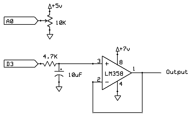
The circuit below demonstrates how you can use an op-amp to buffer output from an Arduino.
This example is to demonstrate taking the PWM (Pulse Width Modulation) output from an Arduino and convert it into a DC voltage (more or less).
This simple sketch shows how you can read a potentiometer and depending on its position, output a PWM signal:
The PWM output is a square wave, where the 5V output is turned on and off at around 490 Hz. The smaller the value passed to analogWrite the lower the duty cycle is (that is, it is off more often than on).
To convert that into a voltage level that varies we can use an RC filter. This uses a capacitor to smooth out the pulses into a fairly level voltage.
However the RC filter is somewhat sensitive to load. That is, the more load you place on it, the lower the voltage is.
So we can add on a "unity gain" op-amp circuit as a buffer. Now the output of the op-amp does not vary much regardless of load (within the specs of the op-amp).
In order to keep the output in the range 0V to 5V, the op-amp needs a slightly higher supply voltage (pin 8) because it cannot output 5V if its supply voltage is 5V. In fact, it outputs a maximum of about 3.4V with a 5V supply voltage. Something in the order of 7V to 12V would be suitable.
Alternatively, use a "rail to rail" op-amp such as the TS922IN.
This example is to demonstrate taking the PWM (Pulse Width Modulation) output from an Arduino and convert it into a DC voltage (more or less).
This simple sketch shows how you can read a potentiometer and depending on its position, output a PWM signal:
void setup () { }

void loop () {
  analogWrite (3, analogRead (A0) / 4);
}
The PWM output is a square wave, where the 5V output is turned on and off at around 490 Hz. The smaller the value passed to analogWrite the lower the duty cycle is (that is, it is off more often than on).
To convert that into a voltage level that varies we can use an RC filter. This uses a capacitor to smooth out the pulses into a fairly level voltage.
However the RC filter is somewhat sensitive to load. That is, the more load you place on it, the lower the voltage is.
So we can add on a "unity gain" op-amp circuit as a buffer. Now the output of the op-amp does not vary much regardless of load (within the specs of the op-amp).
In order to keep the output in the range 0V to 5V, the op-amp needs a slightly higher supply voltage (pin 8) because it cannot output 5V if its supply voltage is 5V. In fact, it outputs a maximum of about 3.4V with a 5V supply voltage. Something in the order of 7V to 12V would be suitable.
Alternatively, use a "rail to rail" op-amp such as the TS922IN.