This post describes how I interfaced a 8x8 LED matrix with as MAX7219 multiplexing LED driver.
The 8x8 LED matrix chip
The 8x8 LED is this one (BL-M12A881UR-11):

I got it from Adafruit for around $US 3.95:
http://www.adafruit.com/products/455
The first problem you have with this is trying to work out which pin is pin 1. It isn't particularly obviously marked.
The datasheet for the product shows this:

That seems to imply that pin 1 is the one on the left if you orient the device so that the part number is towards you, as shown on the photo above where the arrow is. This appears to be the case. I marked mine with a dot from a marker pen so I wouldn't lose track of it.
Flipping it over, now pin 1 is on the right, and the other pins follow, as shown:

Wiring it up can be a bit tedious, especially as it is a bit large to fit onto a standard breadboard. I eventually soldered a 16-core ribbon cable to it like this:

The cable is "flipped" at the half-way mark, so that the pin numbers at the other end go from 1 (the red line) to 16 (the other end).
I then soldered the other end of the cable to a 16-pin header block, like this:

That could then be plugged into a breadboard for patching up to the MAX7219.
The MAX7219 multiplexing chip
Now onto the multiplexing chip, the MAX7219.
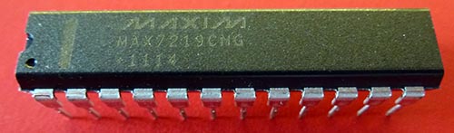
I got this also from Adafruit for around $US 10:
http://www.adafruit.com/products/453
Pinouts:

This chip has the advantage of being a constant current driver, which means you don't need to have lots of resistors between it and the LEDs to stop them drawing too much current. A single resistor connected between the ISET pin (pin 18) and Vcc (not Gnd) lets you set the desired current draw for all LEDs.
This table shows the approximate resistor sizes (in K ohms):

Since the datasheet for the BL-M12A881UR-11 specifies that it has a forward voltage drop of around 2.2V at 20 mA, I chose a 27K resistor as the RSET resistor.
The MAX7219 lets you drive up to 8 x 8-segments LEDs (7 segments plus decimal place), or simply an 8 x 8 matrix like the one I am using.
Once you have downloaded the bit pattern for what you want it to display, it automatically multiplexes that out to the LEDs by sourcing current on the appropriate segments (A to G, plus DP) and then sinking current through digits 0 through to 7, in sequence. The overall effect, since the chip sequences through the digits at about 800 Hz, is that they all appear to be on at once.
Schematic
I wired it up like this:

The 27K resistor sets the output current. The 0.1uF and 10 uF capacitors are recommended to help decouple the power line, and absorb any transient spikes in power required to turn the LEDs on and off.
The 10K "pull-down" resistor on SS is used to stop data being clocked into the chip while the Arduino (or other processor) is being powered up, and the lines at that stage might be "floating".
Note that there are two ground pins: 4 and 9.
I have wired up the DP position before A through to G, because of this table:

To get the bit positions right you need to have DP next to A (and not next to G).
The finished wiring (a bit of a rats nest) looks like this:

Note that we only need 5 wires between the breadboard and the Arduino: +5V, Gnd, MOSI, SCK and SS.
Program code
To send data to the MAX7219 is easy, we just use SPI. To send data we need to send 16 bits, which is a "register" followed by "data", like this:
void sendByte (const byte reg, const byte data)
  {
  digitalWrite (SS, LOW);
  SPI.transfer (reg);
  SPI.transfer (data);
  digitalWrite (SS, HIGH);
  }  // end of sendByte
The registers are as follows:
const byte MAX7219_REG_NOOP        = 0x0;
const byte MAX7219_REG_DIGIT0      = 0x1;
const byte MAX7219_REG_DIGIT1      = 0x2;
const byte MAX7219_REG_DIGIT2      = 0x3;
const byte MAX7219_REG_DIGIT3      = 0x4;
const byte MAX7219_REG_DIGIT4      = 0x5;
const byte MAX7219_REG_DIGIT5      = 0x6;
const byte MAX7219_REG_DIGIT6      = 0x7;
const byte MAX7219_REG_DIGIT7      = 0x8;
const byte MAX7219_REG_DECODEMODE  = 0x9;
const byte MAX7219_REG_INTENSITY   = 0xA;
const byte MAX7219_REG_SCANLIMIT   = 0xB;
const byte MAX7219_REG_SHUTDOWN    = 0xC;
const byte MAX7219_REG_DISPLAYTEST = 0xF;
The NOOP (no operation) register is used when you need to cascade MAX7219 chips together.
Registers 1 through 8 are the digits (where the 8 bits of data are which segments to display for that digit).
The "decode mode" register is used, if required, with ordinary 7-segment displays to have the chip automatically translate numbers into the correct segments. I'm not using that mode here.
The "intensity" mode register lets you set an intensity level (0 to 15) which controls the duty cycle of the PWM sent to the LEDs, and thus how bright they are.
The "scan limit" register can be used if you are using 7-segment displays. Say you only had 4 digits, then by lowering the scan limit they could be brighter, because the chip doesn't waste time trying to send data to digits that don't exist.
The "shutdown" register can be used to blank all digits at once, either because you want them blank for some reason, or to save power.
The "display test" register turns all LEDs on, presumably to test the display.
Font
To display text (like letters, numbers, symbols) I have borrowed the CP437 font from another project. Put this into a "font.h" file:
// bit patterns for the CP437 font

byte cp437_font [256] [8] PROGMEM = {
  { 0x00, 0x00, 0x00, 0x00, 0x00, 0x00, 0x00, 0x00 }, // 0x00
  { 0x7E, 0x81, 0x95, 0xB1, 0xB1, 0x95, 0x81, 0x7E }, // 0x01
  { 0x7E, 0xFF, 0xEB, 0xCF, 0xCF, 0xEB, 0xFF, 0x7E }, // 0x02
  { 0x0E, 0x1F, 0x3F, 0x7E, 0x3F, 0x1F, 0x0E, 0x00 }, // 0x03
  { 0x08, 0x1C, 0x3E, 0x7F, 0x3E, 0x1C, 0x08, 0x00 }, // 0x04
  { 0x18, 0xBA, 0xFF, 0xFF, 0xFF, 0xBA, 0x18, 0x00 }, // 0x05
  { 0x10, 0xB8, 0xFC, 0xFF, 0xFC, 0xB8, 0x10, 0x00 }, // 0x06
  { 0x00, 0x00, 0x18, 0x3C, 0x3C, 0x18, 0x00, 0x00 }, // 0x07
  { 0xFF, 0xFF, 0xE7, 0xC3, 0xC3, 0xE7, 0xFF, 0xFF }, // 0x08
  { 0x00, 0x3C, 0x66, 0x42, 0x42, 0x66, 0x3C, 0x00 }, // 0x09
  { 0xFF, 0xC3, 0x99, 0xBD, 0xBD, 0x99, 0xC3, 0xFF }, // 0x0A
  { 0x70, 0xF8, 0x88, 0x88, 0xFD, 0x7F, 0x07, 0x0F }, // 0x0B
  { 0x00, 0x4E, 0x5F, 0xF1, 0xF1, 0x5F, 0x4E, 0x00 }, // 0x0C
  { 0xC0, 0xE0, 0xFF, 0x7F, 0x05, 0x05, 0x07, 0x07 }, // 0x0D
  { 0xC0, 0xFF, 0x7F, 0x05, 0x05, 0x65, 0x7F, 0x3F }, // 0x0E
  { 0x99, 0x5A, 0x3C, 0xE7, 0xE7, 0x3C, 0x5A, 0x99 }, // 0x0F
  { 0x7F, 0x3E, 0x3E, 0x1C, 0x1C, 0x08, 0x08, 0x00 }, // 0x10
  { 0x08, 0x08, 0x1C, 0x1C, 0x3E, 0x3E, 0x7F, 0x00 }, // 0x11
  { 0x00, 0x24, 0x66, 0xFF, 0xFF, 0x66, 0x24, 0x00 }, // 0x12
  { 0x00, 0x5F, 0x5F, 0x00, 0x00, 0x5F, 0x5F, 0x00 }, // 0x13
  { 0x06, 0x0F, 0x09, 0x7F, 0x7F, 0x01, 0x7F, 0x7F }, // 0x14
  { 0x40, 0xDA, 0xBF, 0xA5, 0xFD, 0x59, 0x03, 0x02 }, // 0x15
  { 0x00, 0x70, 0x70, 0x70, 0x70, 0x70, 0x70, 0x00 }, // 0x16
  { 0x80, 0x94, 0xB6, 0xFF, 0xFF, 0xB6, 0x94, 0x80 }, // 0x17
  { 0x00, 0x04, 0x06, 0x7F, 0x7F, 0x06, 0x04, 0x00 }, // 0x18
  { 0x00, 0x10, 0x30, 0x7F, 0x7F, 0x30, 0x10, 0x00 }, // 0x19
  { 0x08, 0x08, 0x08, 0x2A, 0x3E, 0x1C, 0x08, 0x00 }, // 0x1A
  { 0x08, 0x1C, 0x3E, 0x2A, 0x08, 0x08, 0x08, 0x00 }, // 0x1B
  { 0x3C, 0x3C, 0x20, 0x20, 0x20, 0x20, 0x20, 0x00 }, // 0x1C
  { 0x08, 0x1C, 0x3E, 0x08, 0x08, 0x3E, 0x1C, 0x08 }, // 0x1D
  { 0x30, 0x38, 0x3C, 0x3E, 0x3E, 0x3C, 0x38, 0x30 }, // 0x1E
  { 0x06, 0x0E, 0x1E, 0x3E, 0x3E, 0x1E, 0x0E, 0x06 }, // 0x1F
  { 0x00, 0x00, 0x00, 0x00, 0x00, 0x00, 0x00, 0x00 }, // ' '
  { 0x00, 0x06, 0x5F, 0x5F, 0x06, 0x00, 0x00, 0x00 }, // '!'
  { 0x00, 0x07, 0x07, 0x00, 0x07, 0x07, 0x00, 0x00 }, // '"'
  { 0x14, 0x7F, 0x7F, 0x14, 0x7F, 0x7F, 0x14, 0x00 }, // '#'
  { 0x24, 0x2E, 0x6B, 0x6B, 0x3A, 0x12, 0x00, 0x00 }, // '$'
  { 0x46, 0x66, 0x30, 0x18, 0x0C, 0x66, 0x62, 0x00 }, // '%'
  { 0x30, 0x7A, 0x4F, 0x5D, 0x37, 0x7A, 0x48, 0x00 }, // '&'
  { 0x04, 0x07, 0x03, 0x00, 0x00, 0x00, 0x00, 0x00 }, // '''
  { 0x00, 0x1C, 0x3E, 0x63, 0x41, 0x00, 0x00, 0x00 }, // '('
  { 0x00, 0x41, 0x63, 0x3E, 0x1C, 0x00, 0x00, 0x00 }, // ')'
  { 0x08, 0x2A, 0x3E, 0x1C, 0x1C, 0x3E, 0x2A, 0x08 }, // '*'
  { 0x08, 0x08, 0x3E, 0x3E, 0x08, 0x08, 0x00, 0x00 }, // '+'
  { 0x00, 0x80, 0xE0, 0x60, 0x00, 0x00, 0x00, 0x00 }, // ','
  { 0x08, 0x08, 0x08, 0x08, 0x08, 0x08, 0x00, 0x00 }, // '-'
  { 0x00, 0x00, 0x60, 0x60, 0x00, 0x00, 0x00, 0x00 }, // '.'
  { 0x60, 0x30, 0x18, 0x0C, 0x06, 0x03, 0x01, 0x00 }, // '/'
  { 0x3E, 0x7F, 0x71, 0x59, 0x4D, 0x7F, 0x3E, 0x00 }, // '0'
  { 0x40, 0x42, 0x7F, 0x7F, 0x40, 0x40, 0x00, 0x00 }, // '1'
  { 0x62, 0x73, 0x59, 0x49, 0x6F, 0x66, 0x00, 0x00 }, // '2'
  { 0x22, 0x63, 0x49, 0x49, 0x7F, 0x36, 0x00, 0x00 }, // '3'
  { 0x18, 0x1C, 0x16, 0x53, 0x7F, 0x7F, 0x50, 0x00 }, // '4'
  { 0x27, 0x67, 0x45, 0x45, 0x7D, 0x39, 0x00, 0x00 }, // '5'
  { 0x3C, 0x7E, 0x4B, 0x49, 0x79, 0x30, 0x00, 0x00 }, // '6'
  { 0x03, 0x03, 0x71, 0x79, 0x0F, 0x07, 0x00, 0x00 }, // '7'
  { 0x36, 0x7F, 0x49, 0x49, 0x7F, 0x36, 0x00, 0x00 }, // '8'
  { 0x06, 0x4F, 0x49, 0x69, 0x3F, 0x1E, 0x00, 0x00 }, // '9'
  { 0x00, 0x00, 0x66, 0x66, 0x00, 0x00, 0x00, 0x00 }, // ':'
  { 0x00, 0x80, 0xE6, 0x66, 0x00, 0x00, 0x00, 0x00 }, // ';'
  { 0x08, 0x1C, 0x36, 0x63, 0x41, 0x00, 0x00, 0x00 }, // '<'
  { 0x24, 0x24, 0x24, 0x24, 0x24, 0x24, 0x00, 0x00 }, // '='
  { 0x00, 0x41, 0x63, 0x36, 0x1C, 0x08, 0x00, 0x00 }, // '>'
  { 0x02, 0x03, 0x51, 0x59, 0x0F, 0x06, 0x00, 0x00 }, // '?'
  { 0x3E, 0x7F, 0x41, 0x5D, 0x5D, 0x1F, 0x1E, 0x00 }, // '@'
  { 0x7C, 0x7E, 0x13, 0x13, 0x7E, 0x7C, 0x00, 0x00 }, // 'A'
  { 0x41, 0x7F, 0x7F, 0x49, 0x49, 0x7F, 0x36, 0x00 }, // 'B'
  { 0x1C, 0x3E, 0x63, 0x41, 0x41, 0x63, 0x22, 0x00 }, // 'C'
  { 0x41, 0x7F, 0x7F, 0x41, 0x63, 0x3E, 0x1C, 0x00 }, // 'D'
  { 0x41, 0x7F, 0x7F, 0x49, 0x5D, 0x41, 0x63, 0x00 }, // 'E'
  { 0x41, 0x7F, 0x7F, 0x49, 0x1D, 0x01, 0x03, 0x00 }, // 'F'
  { 0x1C, 0x3E, 0x63, 0x41, 0x51, 0x73, 0x72, 0x00 }, // 'G'
  { 0x7F, 0x7F, 0x08, 0x08, 0x7F, 0x7F, 0x00, 0x00 }, // 'H'
  { 0x00, 0x41, 0x7F, 0x7F, 0x41, 0x00, 0x00, 0x00 }, // 'I'
  { 0x30, 0x70, 0x40, 0x41, 0x7F, 0x3F, 0x01, 0x00 }, // 'J'
  { 0x41, 0x7F, 0x7F, 0x08, 0x1C, 0x77, 0x63, 0x00 }, // 'K'
  { 0x41, 0x7F, 0x7F, 0x41, 0x40, 0x60, 0x70, 0x00 }, // 'L'
  { 0x7F, 0x7F, 0x0E, 0x1C, 0x0E, 0x7F, 0x7F, 0x00 }, // 'M'
  { 0x7F, 0x7F, 0x06, 0x0C, 0x18, 0x7F, 0x7F, 0x00 }, // 'N'
  { 0x1C, 0x3E, 0x63, 0x41, 0x63, 0x3E, 0x1C, 0x00 }, // 'O'
  { 0x41, 0x7F, 0x7F, 0x49, 0x09, 0x0F, 0x06, 0x00 }, // 'P'
  { 0x1E, 0x3F, 0x21, 0x71, 0x7F, 0x5E, 0x00, 0x00 }, // 'Q'
  { 0x41, 0x7F, 0x7F, 0x09, 0x19, 0x7F, 0x66, 0x00 }, // 'R'
  { 0x26, 0x6F, 0x4D, 0x59, 0x73, 0x32, 0x00, 0x00 }, // 'S'
  { 0x03, 0x41, 0x7F, 0x7F, 0x41, 0x03, 0x00, 0x00 }, // 'T'
  { 0x7F, 0x7F, 0x40, 0x40, 0x7F, 0x7F, 0x00, 0x00 }, // 'U'
  { 0x1F, 0x3F, 0x60, 0x60, 0x3F, 0x1F, 0x00, 0x00 }, // 'V'
  { 0x7F, 0x7F, 0x30, 0x18, 0x30, 0x7F, 0x7F, 0x00 }, // 'W'
  { 0x43, 0x67, 0x3C, 0x18, 0x3C, 0x67, 0x43, 0x00 }, // 'X'
  { 0x07, 0x4F, 0x78, 0x78, 0x4F, 0x07, 0x00, 0x00 }, // 'Y'
  { 0x47, 0x63, 0x71, 0x59, 0x4D, 0x67, 0x73, 0x00 }, // 'Z'
  { 0x00, 0x7F, 0x7F, 0x41, 0x41, 0x00, 0x00, 0x00 }, // '['
  { 0x01, 0x03, 0x06, 0x0C, 0x18, 0x30, 0x60, 0x00 }, // backslash
  { 0x00, 0x41, 0x41, 0x7F, 0x7F, 0x00, 0x00, 0x00 }, // ']'
  { 0x08, 0x0C, 0x06, 0x03, 0x06, 0x0C, 0x08, 0x00 }, // '^'
  { 0x80, 0x80, 0x80, 0x80, 0x80, 0x80, 0x80, 0x80 }, // '_'
  { 0x00, 0x00, 0x03, 0x07, 0x04, 0x00, 0x00, 0x00 }, // '`'
  { 0x20, 0x74, 0x54, 0x54, 0x3C, 0x78, 0x40, 0x00 }, // 'a'
  { 0x41, 0x7F, 0x3F, 0x48, 0x48, 0x78, 0x30, 0x00 }, // 'b'
  { 0x38, 0x7C, 0x44, 0x44, 0x6C, 0x28, 0x00, 0x00 }, // 'c'
  { 0x30, 0x78, 0x48, 0x49, 0x3F, 0x7F, 0x40, 0x00 }, // 'd'
  { 0x38, 0x7C, 0x54, 0x54, 0x5C, 0x18, 0x00, 0x00 }, // 'e'
  { 0x48, 0x7E, 0x7F, 0x49, 0x03, 0x02, 0x00, 0x00 }, // 'f'
  { 0x98, 0xBC, 0xA4, 0xA4, 0xF8, 0x7C, 0x04, 0x00 }, // 'g'
  { 0x41, 0x7F, 0x7F, 0x08, 0x04, 0x7C, 0x78, 0x00 }, // 'h'
  { 0x00, 0x44, 0x7D, 0x7D, 0x40, 0x00, 0x00, 0x00 }, // 'i'
  { 0x60, 0xE0, 0x80, 0x80, 0xFD, 0x7D, 0x00, 0x00 }, // 'j'
  { 0x41, 0x7F, 0x7F, 0x10, 0x38, 0x6C, 0x44, 0x00 }, // 'k'
  { 0x00, 0x41, 0x7F, 0x7F, 0x40, 0x00, 0x00, 0x00 }, // 'l'
  { 0x7C, 0x7C, 0x18, 0x38, 0x1C, 0x7C, 0x78, 0x00 }, // 'm'
  { 0x7C, 0x7C, 0x04, 0x04, 0x7C, 0x78, 0x00, 0x00 }, // 'n'
  { 0x38, 0x7C, 0x44, 0x44, 0x7C, 0x38, 0x00, 0x00 }, // 'o'
  { 0x84, 0xFC, 0xF8, 0xA4, 0x24, 0x3C, 0x18, 0x00 }, // 'p'
  { 0x18, 0x3C, 0x24, 0xA4, 0xF8, 0xFC, 0x84, 0x00 }, // 'q'
  { 0x44, 0x7C, 0x78, 0x4C, 0x04, 0x1C, 0x18, 0x00 }, // 'r'
  { 0x48, 0x5C, 0x54, 0x54, 0x74, 0x24, 0x00, 0x00 }, // 's'
  { 0x00, 0x04, 0x3E, 0x7F, 0x44, 0x24, 0x00, 0x00 }, // 't'
  { 0x3C, 0x7C, 0x40, 0x40, 0x3C, 0x7C, 0x40, 0x00 }, // 'u'
  { 0x1C, 0x3C, 0x60, 0x60, 0x3C, 0x1C, 0x00, 0x00 }, // 'v'
  { 0x3C, 0x7C, 0x70, 0x38, 0x70, 0x7C, 0x3C, 0x00 }, // 'w'
  { 0x44, 0x6C, 0x38, 0x10, 0x38, 0x6C, 0x44, 0x00 }, // 'x'
  { 0x9C, 0xBC, 0xA0, 0xA0, 0xFC, 0x7C, 0x00, 0x00 }, // 'y'
  { 0x4C, 0x64, 0x74, 0x5C, 0x4C, 0x64, 0x00, 0x00 }, // 'z'
  { 0x08, 0x08, 0x3E, 0x77, 0x41, 0x41, 0x00, 0x00 }, // '{'
  { 0x00, 0x00, 0x00, 0x77, 0x77, 0x00, 0x00, 0x00 }, // '|'
  { 0x41, 0x41, 0x77, 0x3E, 0x08, 0x08, 0x00, 0x00 }, // '}'
  { 0x02, 0x03, 0x01, 0x03, 0x02, 0x03, 0x01, 0x00 }, // '~'
  { 0x70, 0x78, 0x4C, 0x46, 0x4C, 0x78, 0x70, 0x00 }, // 0x7F
  { 0x0E, 0x9F, 0x91, 0xB1, 0xFB, 0x4A, 0x00, 0x00 }, // 0x80
  { 0x3A, 0x7A, 0x40, 0x40, 0x7A, 0x7A, 0x40, 0x00 }, // 0x81
  { 0x38, 0x7C, 0x54, 0x55, 0x5D, 0x19, 0x00, 0x00 }, // 0x82
  { 0x02, 0x23, 0x75, 0x55, 0x55, 0x7D, 0x7B, 0x42 }, // 0x83
  { 0x21, 0x75, 0x54, 0x54, 0x7D, 0x79, 0x40, 0x00 }, // 0x84
  { 0x21, 0x75, 0x55, 0x54, 0x7C, 0x78, 0x40, 0x00 }, // 0x85
  { 0x20, 0x74, 0x57, 0x57, 0x7C, 0x78, 0x40, 0x00 }, // 0x86
  { 0x18, 0x3C, 0xA4, 0xA4, 0xE4, 0x40, 0x00, 0x00 }, // 0x87
  { 0x02, 0x3B, 0x7D, 0x55, 0x55, 0x5D, 0x1B, 0x02 }, // 0x88
  { 0x39, 0x7D, 0x54, 0x54, 0x5D, 0x19, 0x00, 0x00 }, // 0x89
  { 0x39, 0x7D, 0x55, 0x54, 0x5C, 0x18, 0x00, 0x00 }, // 0x8A
  { 0x01, 0x45, 0x7C, 0x7C, 0x41, 0x01, 0x00, 0x00 }, // 0x8B
  { 0x02, 0x03, 0x45, 0x7D, 0x7D, 0x43, 0x02, 0x00 }, // 0x8C
  { 0x01, 0x45, 0x7D, 0x7C, 0x40, 0x00, 0x00, 0x00 }, // 0x8D
  { 0x79, 0x7D, 0x16, 0x12, 0x16, 0x7D, 0x79, 0x00 }, // 0x8E
  { 0x70, 0x78, 0x2B, 0x2B, 0x78, 0x70, 0x00, 0x00 }, // 0x8F
  { 0x44, 0x7C, 0x7C, 0x55, 0x55, 0x45, 0x00, 0x00 }, // 0x90
  { 0x20, 0x74, 0x54, 0x54, 0x7C, 0x7C, 0x54, 0x54 }, // 0x91
  { 0x7C, 0x7E, 0x0B, 0x09, 0x7F, 0x7F, 0x49, 0x00 }, // 0x92
  { 0x32, 0x7B, 0x49, 0x49, 0x7B, 0x32, 0x00, 0x00 }, // 0x93
  { 0x32, 0x7A, 0x48, 0x48, 0x7A, 0x32, 0x00, 0x00 }, // 0x94
  { 0x32, 0x7A, 0x4A, 0x48, 0x78, 0x30, 0x00, 0x00 }, // 0x95
  { 0x3A, 0x7B, 0x41, 0x41, 0x7B, 0x7A, 0x40, 0x00 }, // 0x96
  { 0x3A, 0x7A, 0x42, 0x40, 0x78, 0x78, 0x40, 0x00 }, // 0x97
  { 0x9A, 0xBA, 0xA0, 0xA0, 0xFA, 0x7A, 0x00, 0x00 }, // 0x98
  { 0x01, 0x19, 0x3C, 0x66, 0x66, 0x3C, 0x19, 0x01 }, // 0x99
  { 0x3D, 0x7D, 0x40, 0x40, 0x7D, 0x3D, 0x00, 0x00 }, // 0x9A
  { 0x18, 0x3C, 0x24, 0xE7, 0xE7, 0x24, 0x24, 0x00 }, // 0x9B
  { 0x68, 0x7E, 0x7F, 0x49, 0x43, 0x66, 0x20, 0x00 }, // 0x9C
  { 0x2B, 0x2F, 0xFC, 0xFC, 0x2F, 0x2B, 0x00, 0x00 }, // 0x9D
  { 0xFF, 0xFF, 0x09, 0x09, 0x2F, 0xF6, 0xF8, 0xA0 }, // 0x9E
  { 0x40, 0xC0, 0x88, 0xFE, 0x7F, 0x09, 0x03, 0x02 }, // 0x9F
  { 0x20, 0x74, 0x54, 0x55, 0x7D, 0x79, 0x40, 0x00 }, // 0xA0
  { 0x00, 0x44, 0x7D, 0x7D, 0x41, 0x00, 0x00, 0x00 }, // 0xA1
  { 0x30, 0x78, 0x48, 0x4A, 0x7A, 0x32, 0x00, 0x00 }, // 0xA2
  { 0x38, 0x78, 0x40, 0x42, 0x7A, 0x7A, 0x40, 0x00 }, // 0xA3
  { 0x7A, 0x7A, 0x0A, 0x0A, 0x7A, 0x70, 0x00, 0x00 }, // 0xA4
  { 0x7D, 0x7D, 0x19, 0x31, 0x7D, 0x7D, 0x00, 0x00 }, // 0xA5
  { 0x00, 0x26, 0x2F, 0x29, 0x2F, 0x2F, 0x28, 0x00 }, // 0xA6
  { 0x00, 0x26, 0x2F, 0x29, 0x2F, 0x26, 0x00, 0x00 }, // 0xA7
  { 0x30, 0x78, 0x4D, 0x45, 0x60, 0x20, 0x00, 0x00 }, // 0xA8
  { 0x38, 0x38, 0x08, 0x08, 0x08, 0x08, 0x00, 0x00 }, // 0xA9
  { 0x08, 0x08, 0x08, 0x08, 0x38, 0x38, 0x00, 0x00 }, // 0xAA
  { 0x4F, 0x6F, 0x30, 0x18, 0xCC, 0xEE, 0xBB, 0x91 }, // 0xAB
  { 0x4F, 0x6F, 0x30, 0x18, 0x6C, 0x76, 0xFB, 0xF9 }, // 0xAC
  { 0x00, 0x00, 0x00, 0x7B, 0x7B, 0x00, 0x00, 0x00 }, // 0xAD
  { 0x08, 0x1C, 0x36, 0x22, 0x08, 0x1C, 0x36, 0x22 }, // 0xAE
  { 0x22, 0x36, 0x1C, 0x08, 0x22, 0x36, 0x1C, 0x08 }, // 0xAF
  { 0xAA, 0x00, 0x55, 0x00, 0xAA, 0x00, 0x55, 0x00 }, // 0xB0
  { 0xAA, 0x55, 0xAA, 0x55, 0xAA, 0x55, 0xAA, 0x55 }, // 0xB1
  { 0xDD, 0xFF, 0xAA, 0x77, 0xDD, 0xAA, 0xFF, 0x77 }, // 0xB2
  { 0x00, 0x00, 0x00, 0xFF, 0xFF, 0x00, 0x00, 0x00 }, // 0xB3
  { 0x10, 0x10, 0x10, 0xFF, 0xFF, 0x00, 0x00, 0x00 }, // 0xB4
  { 0x14, 0x14, 0x14, 0xFF, 0xFF, 0x00, 0x00, 0x00 }, // 0xB5
  { 0x10, 0x10, 0xFF, 0xFF, 0x00, 0xFF, 0xFF, 0x00 }, // 0xB6
  { 0x10, 0x10, 0xF0, 0xF0, 0x10, 0xF0, 0xF0, 0x00 }, // 0xB7
  { 0x14, 0x14, 0x14, 0xFC, 0xFC, 0x00, 0x00, 0x00 }, // 0xB8
  { 0x14, 0x14, 0xF7, 0xF7, 0x00, 0xFF, 0xFF, 0x00 }, // 0xB9
  { 0x00, 0x00, 0xFF, 0xFF, 0x00, 0xFF, 0xFF, 0x00 }, // 0xBA
  { 0x14, 0x14, 0xF4, 0xF4, 0x04, 0xFC, 0xFC, 0x00 }, // 0xBB
  { 0x14, 0x14, 0x17, 0x17, 0x10, 0x1F, 0x1F, 0x00 }, // 0xBC
  { 0x10, 0x10, 0x1F, 0x1F, 0x10, 0x1F, 0x1F, 0x00 }, // 0xBD
  { 0x14, 0x14, 0x14, 0x1F, 0x1F, 0x00, 0x00, 0x00 }, // 0xBE
  { 0x10, 0x10, 0x10, 0xF0, 0xF0, 0x00, 0x00, 0x00 }, // 0xBF
  { 0x00, 0x00, 0x00, 0x1F, 0x1F, 0x10, 0x10, 0x10 }, // 0xC0
  { 0x10, 0x10, 0x10, 0x1F, 0x1F, 0x10, 0x10, 0x10 }, // 0xC1
  { 0x10, 0x10, 0x10, 0xF0, 0xF0, 0x10, 0x10, 0x10 }, // 0xC2
  { 0x00, 0x00, 0x00, 0xFF, 0xFF, 0x10, 0x10, 0x10 }, // 0xC3
  { 0x10, 0x10, 0x10, 0x10, 0x10, 0x10, 0x10, 0x10 }, // 0xC4
  { 0x10, 0x10, 0x10, 0xFF, 0xFF, 0x10, 0x10, 0x10 }, // 0xC5
  { 0x00, 0x00, 0x00, 0xFF, 0xFF, 0x14, 0x14, 0x14 }, // 0xC6
  { 0x00, 0x00, 0xFF, 0xFF, 0x00, 0xFF, 0xFF, 0x10 }, // 0xC7
  { 0x00, 0x00, 0x1F, 0x1F, 0x10, 0x17, 0x17, 0x14 }, // 0xC8
  { 0x00, 0x00, 0xFC, 0xFC, 0x04, 0xF4, 0xF4, 0x14 }, // 0xC9
  { 0x14, 0x14, 0x17, 0x17, 0x10, 0x17, 0x17, 0x14 }, // 0xCA
  { 0x14, 0x14, 0xF4, 0xF4, 0x04, 0xF4, 0xF4, 0x14 }, // 0xCB
  { 0x00, 0x00, 0xFF, 0xFF, 0x00, 0xF7, 0xF7, 0x14 }, // 0xCC
  { 0x14, 0x14, 0x14, 0x14, 0x14, 0x14, 0x14, 0x14 }, // 0xCD
  { 0x14, 0x14, 0xF7, 0xF7, 0x00, 0xF7, 0xF7, 0x14 }, // 0xCE
  { 0x14, 0x14, 0x14, 0x17, 0x17, 0x14, 0x14, 0x14 }, // 0xCF
  { 0x10, 0x10, 0x1F, 0x1F, 0x10, 0x1F, 0x1F, 0x10 }, // 0xD0
  { 0x14, 0x14, 0x14, 0xF4, 0xF4, 0x14, 0x14, 0x14 }, // 0xD1
  { 0x10, 0x10, 0xF0, 0xF0, 0x10, 0xF0, 0xF0, 0x10 }, // 0xD2
  { 0x00, 0x00, 0x1F, 0x1F, 0x10, 0x1F, 0x1F, 0x10 }, // 0xD3
  { 0x00, 0x00, 0x00, 0x1F, 0x1F, 0x14, 0x14, 0x14 }, // 0xD4
  { 0x00, 0x00, 0x00, 0xFC, 0xFC, 0x14, 0x14, 0x14 }, // 0xD5
  { 0x00, 0x00, 0xF0, 0xF0, 0x10, 0xF0, 0xF0, 0x10 }, // 0xD6
  { 0x10, 0x10, 0xFF, 0xFF, 0x10, 0xFF, 0xFF, 0x10 }, // 0xD7
  { 0x14, 0x14, 0x14, 0xFF, 0xFF, 0x14, 0x14, 0x14 }, // 0xD8
  { 0x10, 0x10, 0x10, 0x1F, 0x1F, 0x00, 0x00, 0x00 }, // 0xD9
  { 0x00, 0x00, 0x00, 0xF0, 0xF0, 0x10, 0x10, 0x10 }, // 0xDA
  { 0xFF, 0xFF, 0xFF, 0xFF, 0xFF, 0xFF, 0xFF, 0xFF }, // 0xDB
  { 0xF0, 0xF0, 0xF0, 0xF0, 0xF0, 0xF0, 0xF0, 0xF0 }, // 0xDC
  { 0xFF, 0xFF, 0xFF, 0xFF, 0x00, 0x00, 0x00, 0x00 }, // 0xDD
  { 0x00, 0x00, 0x00, 0x00, 0xFF, 0xFF, 0xFF, 0xFF }, // 0xDE
  { 0x0F, 0x0F, 0x0F, 0x0F, 0x0F, 0x0F, 0x0F, 0x0F }, // 0xDF
  { 0x38, 0x7C, 0x44, 0x6C, 0x38, 0x6C, 0x44, 0x00 }, // 0xE0
  { 0xFC, 0xFE, 0x2A, 0x2A, 0x3E, 0x14, 0x00, 0x00 }, // 0xE1
  { 0x7E, 0x7E, 0x02, 0x02, 0x06, 0x06, 0x00, 0x00 }, // 0xE2
  { 0x02, 0x7E, 0x7E, 0x02, 0x7E, 0x7E, 0x02, 0x00 }, // 0xE3
  { 0x63, 0x77, 0x5D, 0x49, 0x63, 0x63, 0x00, 0x00 }, // 0xE4
  { 0x38, 0x7C, 0x44, 0x7C, 0x3C, 0x04, 0x04, 0x00 }, // 0xE5
  { 0x80, 0xFE, 0x7E, 0x20, 0x20, 0x3E, 0x1E, 0x00 }, // 0xE6
  { 0x04, 0x06, 0x02, 0x7E, 0x7C, 0x06, 0x02, 0x00 }, // 0xE7
  { 0x99, 0xBD, 0xE7, 0xE7, 0xBD, 0x99, 0x00, 0x00 }, // 0xE8
  { 0x1C, 0x3E, 0x6B, 0x49, 0x6B, 0x3E, 0x1C, 0x00 }, // 0xE9
  { 0x4C, 0x7E, 0x73, 0x01, 0x73, 0x7E, 0x4C, 0x00 }, // 0xEA
  { 0x30, 0x78, 0x4A, 0x4F, 0x7D, 0x39, 0x00, 0x00 }, // 0xEB
  { 0x18, 0x3C, 0x24, 0x3C, 0x3C, 0x24, 0x3C, 0x18 }, // 0xEC
  { 0x98, 0xFC, 0x64, 0x3C, 0x3E, 0x27, 0x3D, 0x18 }, // 0xED
  { 0x1C, 0x3E, 0x6B, 0x49, 0x49, 0x00, 0x00, 0x00 }, // 0xEE
  { 0x7E, 0x7F, 0x01, 0x01, 0x7F, 0x7E, 0x00, 0x00 }, // 0xEF
  { 0x2A, 0x2A, 0x2A, 0x2A, 0x2A, 0x2A, 0x00, 0x00 }, // 0xF0
  { 0x44, 0x44, 0x5F, 0x5F, 0x44, 0x44, 0x00, 0x00 }, // 0xF1
  { 0x40, 0x51, 0x5B, 0x4E, 0x44, 0x40, 0x00, 0x00 }, // 0xF2
  { 0x40, 0x44, 0x4E, 0x5B, 0x51, 0x40, 0x00, 0x00 }, // 0xF3
  { 0x00, 0x00, 0x00, 0xFE, 0xFF, 0x01, 0x07, 0x06 }, // 0xF4
  { 0x60, 0xE0, 0x80, 0xFF, 0x7F, 0x00, 0x00, 0x00 }, // 0xF5
  { 0x08, 0x08, 0x6B, 0x6B, 0x08, 0x08, 0x00, 0x00 }, // 0xF6
  { 0x24, 0x36, 0x12, 0x36, 0x24, 0x36, 0x12, 0x00 }, // 0xF7
  { 0x00, 0x06, 0x0F, 0x09, 0x0F, 0x06, 0x00, 0x00 }, // 0xF8
  { 0x00, 0x00, 0x00, 0x18, 0x18, 0x00, 0x00, 0x00 }, // 0xF9
  { 0x00, 0x00, 0x00, 0x10, 0x10, 0x00, 0x00, 0x00 }, // 0xFA
  { 0x10, 0x30, 0x70, 0xC0, 0xFF, 0xFF, 0x01, 0x01 }, // 0xFB
  { 0x00, 0x1F, 0x1F, 0x01, 0x1F, 0x1E, 0x00, 0x00 }, // 0xFC
  { 0x00, 0x19, 0x1D, 0x17, 0x12, 0x00, 0x00, 0x00 }, // 0xFD
  { 0x00, 0x00, 0x3C, 0x3C, 0x3C, 0x3C, 0x00, 0x00 }, // 0xFE
  { 0x00, 0x00, 0x00, 0x00, 0x00, 0x00, 0x00, 0x00 }, // 0xFF
};  //  end of cp437_font
They look like this:

This is stored in PROGMEM to save RAM in your sketch. To send a letter we just grab the 8 bytes (per character) and send them to the display like this:
 void letter (const byte c)
 {
  for (byte col = 0; col < 8; col++)
    sendByte (col + 1, pgm_read_byte (&cp437_font [c] [col]));
 }  // end of letter
We add one to the column because the digits are 1 to 8, not 0 to 7.
We can send a string of characters like this:
void showString (const char * s, const unsigned long time)
{
  char c;
  while (c = *s++)
    {
    letter (c);
    delay (time);
    letter (' ');  // brief gap between letters
    delay (10);
    }
}  // end of showString
Since I only had one matrix, I displayed a string a letter at a time, with a specified pause for you to view it. There is also a brief blank interval between letters (for things like "ee" in "greet") so the flicker shows you have changed letters.
The whole sketch is as follows:
#include <SPI.h>
#include <avr/pgmspace.h>
#include "font.h"

const byte SS = 10;  // omit this line for Arduino 1.0 onwards

 // define max7219 registers
const byte MAX7219_REG_NOOP        = 0x0;
const byte MAX7219_REG_DIGIT0      = 0x1;
const byte MAX7219_REG_DIGIT1      = 0x2;
const byte MAX7219_REG_DIGIT2      = 0x3;
const byte MAX7219_REG_DIGIT3      = 0x4;
const byte MAX7219_REG_DIGIT4      = 0x5;
const byte MAX7219_REG_DIGIT5      = 0x6;
const byte MAX7219_REG_DIGIT6      = 0x7;
const byte MAX7219_REG_DIGIT7      = 0x8;
const byte MAX7219_REG_DECODEMODE  = 0x9;
const byte MAX7219_REG_INTENSITY   = 0xA;
const byte MAX7219_REG_SCANLIMIT   = 0xB;
const byte MAX7219_REG_SHUTDOWN    = 0xC;
const byte MAX7219_REG_DISPLAYTEST = 0xF;


void sendByte (const byte reg, const byte data)
  {
  digitalWrite (SS, LOW);
  SPI.transfer (reg);
  SPI.transfer (data);
  digitalWrite (SS, HIGH);
  }  // end of sendByte


void letter (const byte c)
 {
  for (byte col = 0; col < 8; col++)
    sendByte (col + 1, pgm_read_byte (&cp437_font [c] [col]));
 }  // end of letter

void showString (const char * s, const unsigned long time)
{
  char c;
  while (c = *s++)
    {
    letter (c);
    delay (time);
    letter (' ');  // brief gap between letters
    delay (10);
    }
}  // end of showString

void setup () {

  SPI.begin ();

  sendByte (MAX7219_REG_SCANLIMIT, 7);   // show all 8 digits
  sendByte (MAX7219_REG_DECODEMODE, 0);  // using an led matrix (not digits)
  sendByte (MAX7219_REG_DISPLAYTEST, 0); // no display test

  // clear display
  for (byte col = 0; col < 8; col++)
    sendByte (col + 1, 0);

  sendByte (MAX7219_REG_INTENSITY, 7);  // character intensity: range: 0 to 15
  sendByte (MAX7219_REG_SHUTDOWN, 1);   // not in shutdown mode (ie. start it up)

}   // end of setup

void loop ()
 {
 showString ("Nick Gammon greets you! ", 500);
 }  // end of loop
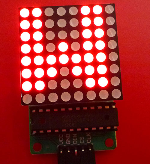
Finished!
Photo of it in operation, displaying the lower-case letter "c":
 |