This page can be quickly reached from the link: http://www.gammon.com.au/lcd
Text LCD displays are all very well, but they suffer from various limitations. For one thing, you don't have a huge amount of screen to play with, you can't do special effects (like inverse) and you can't draw boxes and gauges.
Enter the graphical LCD, which gives you more room to play with, at the expense of needing a lot of wires to connect to your processor.
I bought a "Graphic KS0108 LCD 128x64" from Adafruit for $US 24, which is pretty reasonable. Compare that price to the one for "Standard LCD 20x4" which is $US 18.
The graphical LCD has a resolution of 128 by 64 pixels. It is monochrome, however it has an LED backlight to help see the image (you don't have to connect it, of course).
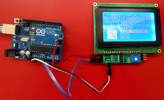
As you can see from the photo, you can fit 8 lines of text, with each line being 21 characters. The font is 6 pixels wide, which means you can fit just over 21 of them into 128 pixels. This includes a one-pixel space between letters. The font is 8 pixels deep, which means you can fit 8 lines of them into 64 pixels. The 8 pixels includes a single pixel of space between each line. So basically for another $US 6 you get over twice the number of characters, plus you can draw boxes and other special characters.
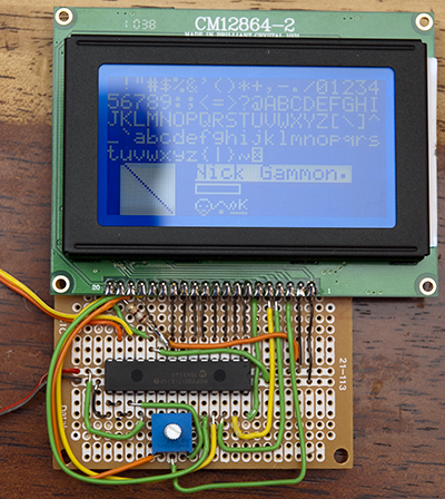
Rather than connecting up the 13 wires need for operation (8 data bits, plus 5 control lines), plus also power and ground, I decided to try to limit the number of connections to the Arduino to only four: Power (+5V), Ground, and the I2C data connections SDA and SCL. The end result is here, notice the four wires only connecting to the Arduino (circled):

Admittedly there are quite a few wires on the breadboard, but it only took about an hour to calmly connect them up, and in any case that is a good candidate for a nice small printed circuit board which could fit on the back of the LCD.
[EDIT] Photo is slightly out-of-date. I swapped some wires around in the wiring diagrams below to make it easier to make printed circuit boards without tracks crossing.
More information about I2C here:
http://www.gammon.com.au/forum/?id=10896
The 13 signal wires to the LCD are provided by connecting to a 16-bit I/IO expander MCP23017 which I purchased for $AUD 2.30 (I found them on a USA site for $US 1.20). The MCP23017 in turn only needs to be connected to power, ground, SDA and SCL, which are the four wires connecting the two boards.
The tricky part was getting the graphics drawing going. I know there are some nice libraries out there for the graphics LCD displays, but they seem to all assume that you are directly connecting the data ports (effectively using up most of the free ports on your processor).
The library that I wrote supports the following operations (visible in the photo):

- Drawing text, either individual letters or a null-terminated string, using an inbuilt font (5 x 7 pixels). Text can be drawn normally or in inverse.
- Clearing the entire screen or any portion to white or black. Since the display hardware draws a byte at a time vertically, the fastest clearing is if you stick to a multiple of 8 pixels, vertically.
- Filling any rectangle, even one not aligned on 8-pixel boundaries. This is much slower than the fast clearing operation.
- Framing a rectangle (drawing a box). The frame can be one or more pixels wide (the more pixels wide, the slower).
- Drawing single-pixel lines, vertically, horizontally or diagonally (in white or black).
- Drawing single pixels (eg. for plotting a graph)
- "Blitting" bitmaps onto the screen. This is pretty fast and could be used for drawing logos, icons etc. Examples are the three icons on the bottom line of the screen.
The wiring is documented below.
I/O Expander basics
The first programming challenge was working out how the I/O expander worked. Basically it is pretty simple. The chip provides two 8-bit ports named A and B. Each bit can individually be programmed as inputs or outputs. Then you basically write to the chip, generally using two bytes:
- The "register" on the chip - that is, what you want it to do
- The data to be put into that register
By way of example, here is how you configure Port A to be all outputs:
Wire.beginTransmission (0x20);  // expander has I2C address 0x20
Wire.send (0x00);   // register 0 is the I/O direction register for Port A
Wire.send (0x00);   //  0x00 for all pins to output mode, 0xFF for all pins to input mode
Wire.endTransmission ();
Now to write 0x56 to port A we would do this:
Wire.beginTransmission (0x20);  // expander has I2C address 0x20
Wire.send (0x12);   // register 0x12 is the I/O port "A"
Wire.send (0x56);   //  what to put on that port
Wire.endTransmission ();
Reading is somewhat similar (ie. to read pixel data from the LCD). To do that we set the data port as inputs, command the LCD to give us some data, and then:
Wire.requestFrom (0x20, (byte) 1);
byte data = Wire.receive ();
Now "data" is the data received from the LCD.
That's basically it for the I/O expander, but it took some research and scratching of my head trying to understand their data sheet before it all went smoothly. ;)
Expander pinouts:


Graphics LCD basics
Now on to the LCD. It has 14 ports that we are interested in. Eight of them are just data (you write or read in bytes, that is, you set or get 8 pixels at a time). I connected those to the "B" port on the I/O expander (because it was closer, basically).
LCD data pins:
- LCD pin 7 goes to MCP23017 pin 1 (Data bit 0)
- LCD pin 8 goes to MCP23017 pin 2 (Data bit 1)
- LCD pin 9 goes to MCP23017 pin 3 (Data bit 2)
- LCD pin 10 goes to MCP23017 pin 4 (Data bit 3)
- LCD pin 11 goes to MCP23017 pin 5 (Data bit 4)
- LCD pin 12 goes to MCP23017 pin 6 (Data bit 5)
- LCD pin 13 goes to MCP23017 pin 7 (Data bit 6)
- LCD pin 14 goes to MCP23017 pin 8 (Data bit 7)
The other six are:
- Data (1) or Instruction (0) - this controls whether the byte on the data ports is considered to be an instruction to the display unit, or simply data to be displayed.
- Read (1) or Write (0) - this controls whether we want to read the pixel data from the LCD's internal memory, or write to it (thus changing the display)
- Enable. The display ignores all the other pins until the Enable pin is brought from high (1) to low (0). Thus you set up everything in advance, and then toggle Enable from high to low. There is no documented maximum time it can be low, so I just leave it low until I am ready to write (or read) more data from it.
- Reset. This is initially low (when the chip is powered on). Then it is brought high to reset the LCD circuitry. This is (now) done under software control to provide the proper reset timing.
- Chip select 1 - if high (1) then the internal chip 1 is selected.
- Chip select 2 - if high (1) then the internal chip 2 is selected.
The purpose of the chip select lines is that the display actually has two chips on it, each handling 64 x 64 pixels. Thus to draw to the left side, you select chip 1, and to draw to the right side, you select chip 2.
I connected all six of those to Port "A" of the I/O expander, and then by judicious setting of the contents of port A, I could toggle various pins on and off.
LCD control pins:
- LCD pin 6 goes to MCP23017 pin 28 (Enable)
- LCD pin 5 goes to MCP23017 pin 27 (Read/Write)
- LCD pin 4 goes to MCP23017 pin 26 (Data/Instruction)
- LCD pin 17 goes to MCP23017 pin 25 (Reset)
- LCD pin 16 goes to MCP23017 pin 24 (CS2)
- LCD pin 15 goes to MCP23017 pin 23 (CS1)
Pins 21 and 22 of the I/O expander are not used (the two low-order bits of Port A). Nor are pins 19 and 20 which are the interrupt output pins.
LCD other pins:
Other pins on the LCD display are connected as follows:
- Pin 1 : LCD logic ground
- Pin 2 : LCD logic power (+5V )
- Pin 3 : Contrast - connect to contrast pot, middle (wiper)
- Pin 18 : Negative voltage (about -9V) - connect to contrast pot, one side (see below for wiring)
- Pin 19 : Power supply for LED light (+5V) (see below about possible resistor)
- Pin 20 : Ground for LED light
Note that for the display to be visible you need to connect up the contrast potentiometer (variable resistor). One side of the pot goes to ground, the other side to pin 18 (which supplies a negative voltage, about -9V). The middle of the pot (the wiper) goes to pin 3. If you connect the third pin of the pot (other than ground and the wiper) to +5V then you won't see anything (unlike some other LCD displays).
Also you might put a 220 ohm resistor in series with the supply to pin 19. This makes the LED light a little less bright and obtrusive. It probably also stops the image burning into the display as quickly.
Other pins on the MCP23017:
- Pin 9 : +5V Power for MCP23017
- Pin 10 : GND Ground for MCP23017
- Pin 11 : SS (Slave Select) - connect to Arduino pin D10 if using SPI (for I2C leave unconnected)
- Pin 12 : SCL (Clock) - connect to Arduino pin A5 for I2C (or D13 for SPI SCK)
- Pin 13 : SDA (Data) - connect to Arduino pin A4 for I2C (or D11 for SPI MOSI)
- Pin 14 : MISO (SPI slave out) - connect to Arduino pin D12 if using SPI (for I2C leave unconnected)
- Pin 15 : Address jumper 0 - connect to ground
- Pin 16 : Address jumper 1 - connect to ground
- Pin 17 : Address jumper 2 - connect to ground
- Pin 18 : Tie to +5V (reset signal)
Other pins should be left unconnected (19, 20, 21, 22)
The address jumper pins could be connected to +5V instead if you wanted a different address. For example, jumpering pin 15 (only) to +5V would make the address of the MCP23017 be 0x21 rather than 0x20.
LCD Memory
This graphic illustrates how the LCD memory is organized:

There are two chips (hence the CS1 (chip select 1) and CS2 (chip select 2)) control lines. Each has 64 x 64 pixels. When you write a byte to the LCD it is written as 8 vertical pixels (vertical, of course, depending on which way you hold it). The first byte at address 0,0 is illustrated as a blue bar. Then the chip's internal memory pointer advances to the right (in the X direction). So, to write a 6-byte glyph we simply write six bytes, letting the pointer increment.
The code detects when you cross the boundary from horizontal position 63 to 64, which is when it needs to change the chip select line from 1 to 2. Then if you keep writing it switches you back to chip 1, but drops the Y coordinate down 8 (effectively going down a byte), so that the next write is 8 pixels lower.
Speed
A lot of effort has gone into making the library reasonably fast, possibly at the expense of fancy features. If drawing is so slow that no-one uses it, all the fancy graphics in the world won't be much use.
The hardware writes a byte at a time (8 pixels) arranged vertically. Thus it is fast to write 8-pixels vertically, but stepping one pixel in the horizontal direction. This lends itself perfectly to drawing text, which is 8 pixels deep (7 plus a 1-pixel gap between lines).
Unfortunately, all of the "set pixel" operations are necessarily slow, because in order to set a single pixel, we first have to read back from the display the current byte there (all 8 pixels), change one of those bits, and then write it back. This is not made any faster by the spec for the LCD display which says you have to read twice to get data from the LCD (one to "latch" the data into the chip, and one to get that data).
We could conceivably buffer the display in the Arduino RAM, but since the display is 128 x 64 / 8 bytes (that is, 1024 bytes) then that would use most or all of the Arduino's memory (depending on the model), just for that buffer.
So, for speed, you are recommended to use one of:
- Draw text (this is done reasonably quickly because the text is in 5 bytes of 8 bits each, per letter).
- "Blit" graphics (this is similar to drawing text)
- Clearing rectangles which are vertically aligned on an 8-pixel boundary. They can be drawn as black or white, so you could use rectangles as "bar gauges" or similar.
Indicative timings:
- Clear entire screen (done at startup): 600 ms (ie. 0.6 seconds)
- Set cursor (change where the next text is to be drawn): 33 ms
- Write text: about 4 ms per letter
- Blit graphics: about 2 ms per byte
- Clear a rectangle (black or white): about 120 ms for a 20 x 50 pixel rectangle. Rectangle must be on 8-pixel boundary vertically.
- Fill a 20 x 50 pixel rectangle: 5230 ms (yes, 5.2 seconds!). Rectangle can be on any boundary.
- Frame a single-pixel border rectangle of 20 x 50 pixels: 730 ms
- Frame a double-pixel border rectangle of 20 x 50 pixels: 1430 ms
Library
Library files can be downloaded from here:
http://www.gammon.com.au/Arduino/I2C_graphical_LCD_display.zip
Also:
https://github.com/nickgammon/I2C_graphical_LCD_display
I2C_graphical_LCD_display.h
/*
 I2C_graphical_LCD_display.h


 Written by Nick Gammon.
 Date: 14 February 2011.

 HISTORY

 Version 1.0 : 15 February 2011
 Version 1.1 : 15 February 2011  -- added write-through cache
 Version 1.2 : 19 February 2011  -- allowed for more than 256 bytes in lcd.blit
 Version 1.3 : 21 February 2011  -- swapped some pins around to make it easier to make circuit boards *
 Version 1.4 : 24 February 2011  -- added code to raise reset line properly, also scrolling code *
 Version 1.5 : 28 February 2011  -- added support for SPI interface
 Version 1.6 : 13 March 2011     -- fixed bug in reading data from SPI interface
 Version 1.7 : 13 April 2011     -- made the bitmap for letter "Q" look a bit better
 Version 1.8 : 10 March 2012     -- adapted to work on Arduino IDE 1.0 onwards
 Version 1.9 : 26 May 2012       -- default to I2C rather than SPI on the begin() function
 -- also increased initial LCD_BUSY_DELAY from 20 to 50 uS
 Version 1.10:  8 July 2012      -- fixed issue with dropping enable before reading from display
 Version 1.11: 15 August 2014    -- added support for Print class, and an inverse mode

 * These changes required hardware changes to pin configurations


 PERMISSION TO DISTRIBUTE

 Permission is hereby granted, free of charge, to any person obtaining a copy of this software
 and associated documentation files (the "Software"), to deal in the Software without restriction,
 including without limitation the rights to use, copy, modify, merge, publish, distribute, sublicense,
 and/or sell copies of the Software, and to permit persons to whom the Software is furnished to do so,
 subject to the following conditions:

 The above copyright notice and this permission notice shall be included in
 all copies or substantial portions of the Software.


 LIMITATION OF LIABILITY

 The software is provided "as is", without warranty of any kind, express or implied,
 including but not limited to the warranties of merchantability, fitness for a particular
 purpose and noninfringement. In no event shall the authors or copyright holders be liable
 for any claim, damages or other liability, whether in an action of contract,
 tort or otherwise, arising from, out of or in connection with the software
 or the use or other dealings in the software.

 */


#ifndef I2C_graphical_LCD_display_H
#define I2C_graphical_LCD_display_H

// #define WRITETHROUGH_CACHE

#if defined(ARDUINO) && ARDUINO >= 100
  #include "Arduino.h"
#else
  #include <WProgram.h>
#endif

#include <avr/pgmspace.h>

// MCP23017 registers (everything except direction defaults to 0)

#define IODIRA   0x00   // IO direction  (0 = output, 1 = input (Default))
#define IODIRB   0x01
#define IOPOLA   0x02   // IO polarity   (0 = normal, 1 = inverse)
#define IOPOLB   0x03
#define GPINTENA 0x04   // Interrupt on change (0 = disable, 1 = enable)
#define GPINTENB 0x05
#define DEFVALA  0x06   // Default comparison for interrupt on change (interrupts on opposite)
#define DEFVALB  0x07
#define INTCONA  0x08   // Interrupt control (0 = interrupt on change from previous, 1 = interrupt on change from DEFVAL)
#define INTCONB  0x09
#define IOCON    0x0A   // IO Configuration: bank/mirror/seqop/disslw/haen/odr/intpol/notimp
//#define IOCON 0x0B  // same as 0x0A
#define GPPUA    0x0C   // Pull-up resistor (0 = disabled, 1 = enabled)
#define GPPUB    0x0D
#define INFTFA   0x0E   // Interrupt flag (read only) : (0 = no interrupt, 1 = pin caused interrupt)
#define INFTFB   0x0F
#define INTCAPA  0x10   // Interrupt capture (read only) : value of GPIO at time of last interrupt
#define INTCAPB  0x11
#define GPIOA    0x12   // Port value. Write to change, read to obtain value
#define GPIOB    0x13
#define OLLATA   0x14   // Output latch. Write to latch output.
#define OLLATB   0x15


/*

 My mappings of the KS0108 registers:


 LCD PIN  MCP23017 PIN  Name   Purpose

 ---- Wire these pins together as shown ------

 --- Port "A" - control lines

  6      28 (GPA7)     E      Enable data transfer on 1 -> 0 transition  (see LCD_ENABLE)
  5      27 (GPA6)     R/~W   1 = read, 0 = write (to LCD) (see LCD_READ)
  4      26 (GPA5)     D/~I   1 = data, 0 = instruction    (see LCD_DATA)
 17      25 (GPA4)     ~RST   1 = not reset, 0 = reset
 16      24 (GPA3)     CS2    Chip select for IC2 (1 = active)  (see LCD_CS2)
 15      23 (GPA2)     CS1    Chip select for IC1 (1 = active)  (see LCD_CS1)

 --- Port "B" - data lines

  7      1  (GPB0)     DB0    Data bit 0
  8      2  (GPB1)     DB1    Data bit 1
  9      3  (GPB2)     DB2    Data bit 2
 10      4  (GPB3)     DB3    Data bit 3
 11      5  (GPB4)     DB4    Data bit 4
 12      6  (GPB5)     DB5    Data bit 5
 13      7  (GPB6)     DB6    Data bit 6
 14      8  (GPB7)     DB7    Data bit 7

 ---- Pins on LCD display which are not connected to the I/O expander ----

  1                    GND    LCD logic ground
  2                    +5V    LCD logic power
  3                    V0     Contrast - connect to contrast pot, middle (wiper)
 17                   ~RST    Tie to +5V via 10K resistor (reset signal)
 18                    Vee    Negative voltage - connect to contrast pot, one side *
 19                    A      Power supply for LED light (+5V)  A=anode
 20                    K      GND for LED light                 K=cathode

 * Third leg of contrast pot is wired to ground.

 ---- Pins on MCP23017 which are not connected to the LCD display ----

  9   (VDD)            +5V    Power for MCP23017
 10   (VSS)            GND    Ground for MCP23017
 11   (CS)             SS     (Slave Select) - connect to Arduino pin D10 if using SPI (D53 on the Mega)
 12   (SCL/SCK)        SCL    (Clock) - connect to Arduino pin A5 for I2C (D21 on the Mega) (for SPI SCK: D13, or D52 on the Mega)
 13   (SDA/SI)         SDA    (Data)  - connect to Arduino pin A4 for I2C (D20 on the Mega) (for SPI MOSI: D11, or D51 on the Mega)
 14   (SO)             MISO   (SPI slave out) - connect to Arduino pin D12 if using SPI (D50 on the Mega)
 15   (A0)             Address jumper 0 - connect to ground (unless you want a different address)
 16   (A1)             Address jumper 1 - connect to ground
 17   (A2)             Address jumper 2 - connect to ground
 18   (~RST)           Tie to +5V via 10K resistor (reset signal)
 19   (INTA)           Interrupt for port A (not used)
 20   (INTB)           Interrupt for port B (not used)
 21   (GPA0)           Not used
 22   (GPA1)           Not used
 23   (GPA2)           Not used

 */


// GPA port - these show which wires from the LCD are connected to which pins on the I/O expander

#define LCD_CS1    0b00000100   // chip select 1  (pin 23)                            0x04
#define LCD_CS2    0b00001000   // chip select 2  (pin 24)                            0x08
#define LCD_RESET  0b00010000   // reset (pin 25)                                     0x10
#define LCD_DATA   0b00100000   // 1xxxxxxx = data; 0xxxxxxx = instruction  (pin 26)  0x20
#define LCD_READ   0b01000000   // x1xxxxxx = read; x0xxxxxx = write  (pin 27)        0x40
#define LCD_ENABLE 0b10000000   // enable by toggling high/low  (pin 28)              0x80


// Commands sent when LCD in "instruction" mode (LCD_DATA bit set to 0)

#define LCD_ON          0x3F
#define LCD_OFF         0x3E
#define LCD_SET_ADD     0x40   // plus X address (0 to 63)
#define LCD_SET_PAGE    0xB8   // plus Y address (0 to 7)
#define LCD_DISP_START  0xC0   // plus X address (0 to 63) - for scrolling

class I2C_graphical_LCD_display : public Print
{
private:

  byte _chipSelect;  // currently-selected chip (LCD_CS1 or LCD_CS2)
  byte _lcdx;        // current x position (0 - 127)
  byte _lcdy;        // current y position (0 - 63)

  byte _port;        // port that the MCP23017 is on (should be 0x20 to 0x27)
  byte _ssPin;       // if non-zero use SPI rather than I2C (and this is the SS pin)

  void expanderWrite (const byte reg, const byte data);
  byte readData ();
  void startSend ();    // prepare for sending to MCP23017  (eg. set SS low)
  void doSend (const byte what);  // send a byte to the MCP23017
  void endSend ();      // finished sending  (eg. set SS high)

  boolean _invmode;


#ifdef WRITETHROUGH_CACHE
  byte _cache [64 * 128 / 8];
  int  _cacheOffset;
#endif

public:

  // constructor
  I2C_graphical_LCD_display () : _port (0x20), _ssPin (10), _invmode(false) {};

  void begin (const byte port = 0x20, const byte i2cAddress = 0, const byte ssPin = 0);
  void cmd (const byte data);
  void gotoxy (byte x, byte y);
  void writeData (byte data, const boolean inv);
  void writeData (byte data) { writeData(data, _invmode);}
  void letter (byte c, const boolean inv);
  void letter (byte c) {letter(c, _invmode);}
  void string (const char * s, const boolean inv);
  void string (const char * s) {string(s, _invmode);}
  void blit (const byte * pic, const unsigned int size);
  void clear (const byte x1 = 0,    // start pixel
              const byte y1 = 0,
              const byte x2 = 127,  // end pixel
              const byte y2 = 63,
              const byte val = 0);   // what to fill with
  void setPixel (const byte x, const byte y, const byte val = 1);
  void fillRect (const byte x1 = 0,   // start pixel
                const byte y1 = 0,
                const byte x2 = 127, // end pixel
                const byte y2 = 63,
                const byte val = 1);  // what to draw (0 = white, 1 = black)
  void frameRect (const byte x1 = 0,    // start pixel
                 const byte y1 = 0,
                 const byte x2 = 127, // end pixel
                 const byte y2 = 63,
                 const byte val = 1,    // what to draw (0 = white, 1 = black)
                 const byte width = 1);
  void line  (const byte x1 = 0,    // start pixel
              const byte y1 = 0,
              const byte x2 = 127,  // end pixel
              const byte y2 = 63,
              const byte val = 1);  // what to draw (0 = white, 1 = black)
  void scroll (const byte y = 0);   // set scroll position

#if defined(ARDUINO) && ARDUINO >= 100
	size_t write(uint8_t c) {letter(c, _invmode); return 1; }
#else
	void write(uint8_t c) { letter(c, _invmode); }
#endif

  void setInv(boolean inv) {_invmode = inv;} // set inverse mode state true == inverse

};

#endif  // I2C_graphical_LCD_display_H
I2C_graphical_LCD_display.cpp
/*
 I2C_graphical_LCD_display.cpp


 Written by Nick Gammon
 Date: 14 February 2011.

 HISTORY

 Version 1.0 : 15 February 2011
 Version 1.1 : 15 February 2011  -- added write-through cache
 Version 1.2 : 19 February 2011  -- allowed for more than 256 bytes in lcd.blit
 Version 1.3 : 21 February 2011  -- swapped some pins around to make it easier to make circuit boards *
 Version 1.4 : 24 February 2011  -- added code to raise reset line properly, also scrolling code *
 Version 1.5 : 28 February 2011  -- added support for SPI interface
 Version 1.6 : 13 March 2011     -- fixed bug in reading data from SPI interface
 Version 1.7 : 13 April 2011     -- made the bitmap for letter "Q" look a bit better
 Version 1.8 : 10 March 2012     -- adapted to work on Arduino IDE 1.0 onwards
 Version 1.9 : 26 May 2012       -- default to I2C rather than SPI on the begin() function
                                 -- also increased initial LCD_BUSY_DELAY from 20 to 50 uS
 Version 1.10:  8 July 2012      -- fixed issue with dropping enable before reading from display
 Version 1.11: 15 August 2014    -- added support for Print class, and an inverse mode


 * These changes required hardware changes to pin configurations

 PERMISSION TO DISTRIBUTE

 Permission is hereby granted, free of charge, to any person obtaining a copy of this software
 and associated documentation files (the "Software"), to deal in the Software without restriction,
 including without limitation the rights to use, copy, modify, merge, publish, distribute, sublicense,
 and/or sell copies of the Software, and to permit persons to whom the Software is furnished to do so,
 subject to the following conditions:

 The above copyright notice and this permission notice shall be included in
 all copies or substantial portions of the Software.


 LIMITATION OF LIABILITY

 The software is provided "as is", without warranty of any kind, express or implied,
 including but not limited to the warranties of merchantability, fitness for a particular
 purpose and noninfringement. In no event shall the authors or copyright holders be liable
 for any claim, damages or other liability, whether in an action of contract,
 tort or otherwise, arising from, out of or in connection with the software
 or the use or other dealings in the software.

 */


#include "I2C_graphical_LCD_display.h"

// WARNING: Put this following line into your main program or you will get compiler errors:
#include <Wire.h>
#include <SPI.h>

// SPI is so fast we need to give the LCD time to catch up.
// This is the number of microseconds we wait. Something like 20 to 50 is probably reasonable.
//  Increase this value if the display is either not working, or losing data.

#define LCD_BUSY_DELAY 50   // microseconds

// font data - each character is 8 pixels deep and 5 pixels wide

const byte font [96] [5] PROGMEM = {
  { 0x00, 0x00, 0x00, 0x00, 0x00 }, // space  (0x20)
  { 0x00, 0x00, 0x2F, 0x00, 0x00 }, // !
  { 0x00, 0x07, 0x00, 0x07, 0x00 }, // "
  { 0x14, 0x7F, 0x14, 0x7F, 0x14 }, // #
  { 0x24, 0x2A, 0x7F, 0x2A, 0x12 }, // $
  { 0x23, 0x13, 0x08, 0x64, 0x62 }, // %
  { 0x36, 0x49, 0x55, 0x22, 0x50 }, // &
  { 0x00, 0x05, 0x03, 0x00, 0x00 }, // '
  { 0x00, 0x1C, 0x22, 0x41, 0x00 }, // (
  { 0x00, 0x41, 0x22, 0x1C, 0x00 }, // (
  { 0x14, 0x08, 0x3E, 0x08, 0x14 }, // *
  { 0x08, 0x08, 0x3E, 0x08, 0x08 }, // +
  { 0x00, 0x50, 0x30, 0x00, 0x00 }, // ,
  { 0x08, 0x08, 0x08, 0x08, 0x08 }, // -
  { 0x00, 0x30, 0x30, 0x00, 0x00 }, // .
  { 0x20, 0x10, 0x08, 0x04, 0x02 }, // /

  { 0x3E, 0x51, 0x49, 0x45, 0x3E }, // 0  (0x30)
  { 0x00, 0x42, 0x7F, 0x40, 0x00 }, // 1
  { 0x42, 0x61, 0x51, 0x49, 0x46 }, // 2
  { 0x21, 0x41, 0x45, 0x4B, 0x31 }, // 3
  { 0x18, 0x14, 0x12, 0x7F, 0x10 }, // 4
  { 0x27, 0x45, 0x45, 0x45, 0x39 }, // 5
  { 0x3C, 0x4A, 0x49, 0x49, 0x30 }, // 6
  { 0x01, 0x71, 0x09, 0x05, 0x03 }, // 7
  { 0x36, 0x49, 0x49, 0x49, 0x36 }, // 8
  { 0x06, 0x49, 0x49, 0x29, 0x1E }, // 9
  { 0x00, 0x36, 0x36, 0x00, 0x00 }, // :
  { 0x00, 0x56, 0x36, 0x00, 0x00 }, // ;
  { 0x08, 0x14, 0x22, 0x41, 0x00 }, // <
  { 0x14, 0x14, 0x14, 0x14, 0x14 }, // =
  { 0x00, 0x41, 0x22, 0x14, 0x08 }, // >
  { 0x02, 0x01, 0x51, 0x09, 0x06 }, // ?

  { 0x32, 0x49, 0x79, 0x41, 0x3E }, // @  (0x40)
  { 0x7E, 0x11, 0x11, 0x11, 0x7E }, // A
  { 0x7F, 0x49, 0x49, 0x49, 0x36 }, // B
  { 0x3E, 0x41, 0x41, 0x41, 0x22 }, // C
  { 0x7F, 0x41, 0x41, 0x22, 0x1C }, // D
  { 0x7F, 0x49, 0x49, 0x49, 0x41 }, // E
  { 0x7F, 0x09, 0x09, 0x09, 0x01 }, // F
  { 0x3E, 0x41, 0x49, 0x49, 0x7A }, // G
  { 0x7F, 0x08, 0x08, 0x08, 0x7F }, // H
  { 0x00, 0x41, 0x7F, 0x41, 0x00 }, // I
  { 0x20, 0x40, 0x41, 0x3F, 0x01 }, // J
  { 0x7F, 0x08, 0x14, 0x22, 0x41 }, // K
  { 0x7F, 0x40, 0x40, 0x40, 0x40 }, // L
  { 0x7F, 0x02, 0x0C, 0x02, 0x7F }, // M
  { 0x7F, 0x04, 0x08, 0x10, 0x7F }, // N
  { 0x3E, 0x41, 0x41, 0x41, 0x3E }, // O

  { 0x3F, 0x09, 0x09, 0x09, 0x06 }, // P  (0x50)
  { 0x3E, 0x41, 0x51, 0x21, 0x5E }, // Q
  { 0x7F, 0x09, 0x19, 0x29, 0x46 }, // R
  { 0x46, 0x49, 0x49, 0x49, 0x31 }, // S
  { 0x01, 0x01, 0x7F, 0x01, 0x01 }, // T
  { 0x3F, 0x40, 0x40, 0x40, 0x3F }, // U
  { 0x1F, 0x20, 0x40, 0x20, 0x1F }, // V
  { 0x3F, 0x40, 0x30, 0x40, 0x3F }, // W
  { 0x63, 0x14, 0x08, 0x14, 0x63 }, // X
  { 0x07, 0x08, 0x70, 0x08, 0x07 }, // Y
  { 0x61, 0x51, 0x49, 0x45, 0x43 }, // Z
  { 0x00, 0x7F, 0x41, 0x41, 0x00 }, // [
  { 0x02, 0x04, 0x08, 0x10, 0x20 }, // backslash
  { 0x00, 0x41, 0x41, 0x7F, 0x00 }, // ]
  { 0x04, 0x02, 0x01, 0x02, 0x04 }, // ^
  { 0x40, 0x40, 0x40, 0x40, 0x40 }, // _

  { 0x00, 0x01, 0x02, 0x04, 0x00 }, // `  (0x60)
  { 0x20, 0x54, 0x54, 0x54, 0x78 }, // a
  { 0x7F, 0x50, 0x48, 0x48, 0x30 }, // b
  { 0x38, 0x44, 0x44, 0x44, 0x20 }, // c
  { 0x38, 0x44, 0x44, 0x48, 0x7F }, // d
  { 0x38, 0x54, 0x54, 0x54, 0x18 }, // e
  { 0x08, 0x7E, 0x09, 0x01, 0x02 }, // f
  { 0x0C, 0x52, 0x52, 0x52, 0x3E }, // g
  { 0x7F, 0x08, 0x04, 0x04, 0x78 }, // h
  { 0x00, 0x44, 0x7D, 0x40, 0x00 }, // i
  { 0x20, 0x40, 0x44, 0x3D, 0x00 }, // j
  { 0x7F, 0x10, 0x28, 0x44, 0x00 }, // k
  { 0x00, 0x41, 0x7F, 0x40, 0x00 }, // l
  { 0x7C, 0x04, 0x18, 0x04, 0x78 }, // m
  { 0x7C, 0x08, 0x04, 0x04, 0x78 }, // n
  { 0x38, 0x44, 0x44, 0x44, 0x38 }, // o

  { 0x7C, 0x14, 0x14, 0x14, 0x08 }, // p  (0x70)
  { 0x08, 0x14, 0x14, 0x08, 0x7C }, // q
  { 0x7C, 0x08, 0x04, 0x04, 0x08 }, // r
  { 0x48, 0x54, 0x54, 0x54, 0x20 }, // s
  { 0x04, 0x3F, 0x44, 0x40, 0x20 }, // t
  { 0x3C, 0x40, 0x40, 0x20, 0x7C }, // u
  { 0x1C, 0x20, 0x40, 0x20, 0x1C }, // v
  { 0x3C, 0x40, 0x30, 0x40, 0x3C }, // w
  { 0x44, 0x28, 0x10, 0x28, 0x44 }, // x
  { 0x0C, 0x50, 0x50, 0x50, 0x3C }, // y
  { 0x44, 0x64, 0x54, 0x4C, 0x44 }, // z
  { 0x00, 0x08, 0x36, 0x41, 0x00 }, // {
  { 0x00, 0x00, 0x7F, 0x00, 0x00 }, // |
  { 0x00, 0x41, 0x36, 0x08, 0x00 }, // }
  { 0x30, 0x08, 0x10, 0x20, 0x18 }, // ~
  { 0x7F, 0x55, 0x49, 0x55, 0x7F }  // unknown char (0x7F)

};

// glue routines for version 1.0+ of the IDE
uint8_t i2c_read ()
{
#if defined(ARDUINO) && ARDUINO >= 100
  return Wire.read ();
#else
  return Wire.receive ();
#endif
} // end of Nunchuk::i2c_read

void i2c_write (int data)
{
#if defined(ARDUINO) && ARDUINO >= 100
  Wire.write (data);
#else
  Wire.send (data);
#endif
} // end of Nunchuk::i2c_write


// prepare for sending to MCP23017
void I2C_graphical_LCD_display::startSend ()
{

  if (_ssPin)
    {
    delayMicroseconds (LCD_BUSY_DELAY);
    digitalWrite (_ssPin, LOW);
    SPI.transfer (_port << 1);
    }
  else
    Wire.beginTransmission (_port);

}  // end of I2C_graphical_LCD_display::startSend

// send a byte via SPI or I2C
void I2C_graphical_LCD_display::doSend (const byte what)
{
  if (_ssPin)
    SPI.transfer (what);
  else
    i2c_write (what);
}  // end of I2C_graphical_LCD_display::doSend

// finish sending to MCP23017
void I2C_graphical_LCD_display::endSend ()
{
  if (_ssPin)
    digitalWrite (_ssPin, HIGH);
  else
    Wire.endTransmission ();

}  // end of I2C_graphical_LCD_display::endSend


// set up - call before using
// specify
//  * the port that the MCP23017 is on (default 0x20)
//  * the i2c port (default 0)
//  * the SPI SS (slave select) pin - leave as default of zero for I2C operation

// turns LCD on, clears memory, sets the cursor to 0,0

// Approx time to run: 600 ms on Arduino Uno
void I2C_graphical_LCD_display::begin (const byte port,
                                       const byte i2cAddress,
                                       const byte ssPin)
{

  _port = port;   // remember port
  _ssPin = ssPin; // and SPI slave select pin

  if (_ssPin)
    SPI.begin ();
  else
    Wire.begin (i2cAddress);

// un-comment next line for faster I2C communications:
//   TWBR = 12;

  // byte mode (not sequential)
  expanderWrite (IOCON, 0b00100000);

  // all pins as outputs
  expanderWrite (IODIRA, 0);
  expanderWrite (IODIRB, 0);

  // take reset line low
  startSend ();
    doSend (GPIOA);
    doSend (0); // all lines low
  endSend ();

  // now raise reset (and enable) line and wait briefly
  expanderWrite (GPIOA, LCD_ENABLE | LCD_RESET);
  delay (1);

  // turn LCD chip 1 on
  _chipSelect = LCD_CS1;
  cmd (LCD_ON);

  // turn LCD chip 2 on
  _chipSelect = LCD_CS2;
  cmd (LCD_ON);

  // clear entire LCD display
  clear ();

  // and put the cursor in the top-left corner
  gotoxy (0, 0);

  // ensure scroll is set to zero
  scroll (0);

}  // end of I2C_graphical_LCD_display::I2C_graphical_LCD_display (constructor)


// send command to LCD display (chip 1 or 2 as in chipSelect variable)
// for example, setting page (Y) or address (X)
void I2C_graphical_LCD_display::cmd (const byte data)
{
  startSend ();
    doSend (GPIOA);                      // control port
    doSend (LCD_RESET | LCD_ENABLE | _chipSelect);   // set enable high (D/I is low meaning instruction)
    doSend (data);                       // (command written to GPIOB)
    doSend (LCD_RESET | _chipSelect);    // (GPIOA again) pull enable low to toggle data
  endSend ();
} // end of I2C_graphical_LCD_display::cmd

// set our "cursor" to the x/y position
// works out whether this refers to chip 1 or chip 2 and sets chipSelect appropriately

// Approx time to run: 33 ms on Arduino Uno
void I2C_graphical_LCD_display::gotoxy (byte x,
                                        byte y)
{

  if (x > 127)
    x = 0;
  if (y > 63)
    y = 0;

#ifdef WRITETHROUGH_CACHE
  _cacheOffset = 0;
#endif

  // work out which chip
  if (x >= 64)
    {
    x -= 64;
    _chipSelect = LCD_CS2;
#ifdef WRITETHROUGH_CACHE
    _cacheOffset = 64 * 64 / 8;  // half-way through cache
#endif

    }
  else
    _chipSelect = LCD_CS1;

  // remember for incrementing later
  _lcdx = x;
  _lcdy = y;

  // command LCD to the correct page and address
  cmd (LCD_SET_PAGE | (y >> 3) );  // 8 pixels to a page
  cmd (LCD_SET_ADD  | x );

#ifdef WRITETHROUGH_CACHE
  _cacheOffset += (x << 3) | y >> 3;
#endif
}  // end of I2C_graphical_LCD_display::gotoxy


// set register "reg" on expander to "data"
// for example, IO direction
void I2C_graphical_LCD_display::expanderWrite (const byte reg,
                                               const byte data )
{
  startSend ();
    doSend (reg);
    doSend (data);
  endSend ();
} // end of I2C_graphical_LCD_display::expanderWrite

// read the byte corresponding to the selected x,y position
byte I2C_graphical_LCD_display::I2C_graphical_LCD_display::readData ()
{

#ifdef WRITETHROUGH_CACHE
  return _cache [_cacheOffset];
#endif

  // data port (on the MCP23017) is now input
  expanderWrite (IODIRB, 0xFF);

  // lol, see the KS0108 spec sheet - you need to read twice to get the data
  startSend ();
    doSend (GPIOA);                  // control port
    doSend (LCD_RESET | LCD_READ | LCD_DATA | LCD_ENABLE | _chipSelect);  // set enable high
  endSend ();

  startSend ();
    doSend (GPIOA);                  // control port
    doSend (LCD_RESET | LCD_READ | LCD_DATA | _chipSelect);  // pull enable low to toggle data
  endSend ();

  startSend ();
  doSend (GPIOA);                  // control port
  doSend (LCD_RESET | LCD_READ | LCD_DATA | LCD_ENABLE | _chipSelect);  // set enable high
  endSend ();

  byte data;

  if (_ssPin)
    {
    digitalWrite (_ssPin, LOW);
    SPI.transfer ((_port << 1) | 1);  // read operation has low-bit set
    SPI.transfer (GPIOB);             // which register to read from
    data = SPI.transfer (0);          // get byte back
    digitalWrite (_ssPin, HIGH);
    }
  else
    {
    // initiate blocking read into internal buffer
    Wire.requestFrom (_port, (byte) 1);

    // don't bother checking if available, Wire.receive does that anyway
    //  also it returns 0x00 if nothing there, so we don't need to bother doing that
    data = i2c_read ();
    }

  // drop enable AFTER we have read it
  startSend ();
  doSend (GPIOA);                  // control port
  doSend (LCD_RESET | LCD_READ | LCD_DATA | _chipSelect);  // pull enable low to toggle data
  endSend ();

  // data port (on the MCP23017) is now output again
  expanderWrite (IODIRB, 0);

  return data;

}  // end of I2C_graphical_LCD_display::readData

// write a byte to the LCD display at the selected x,y position
// if inv true, invert the data
// writing advances the cursor 1 pixel to the right
// it wraps to the next "line" if necessary (a line is 8 pixels deep)
void I2C_graphical_LCD_display::writeData (byte data,
                                           const boolean inv)
{

  // invert data to be written if wanted
  if (inv)
    data ^= 0xFF;

  // note that the MCP23017 automatically toggles between port A and port B
  // so the four sends do this:
  //   1. Choose initial port as GPIOA (general IO port A)
  //   2. Port A: set E high
  //   3. Port B: send the data byte
  //   4. Port A: set E low to toggle the transfer of data

  startSend ();
    doSend (GPIOA);                  // control port
    doSend (LCD_RESET | LCD_DATA | LCD_ENABLE | _chipSelect);  // set enable high
    doSend (data);                   // (screen data written to GPIOB)
    doSend (LCD_RESET | LCD_DATA | _chipSelect);  // (GPIOA again) pull enable low to toggle data
  endSend ();

#ifdef WRITETHROUGH_CACHE
  _cache [_cacheOffset] = data;
#endif

  // we have now moved right one pixel (in the LCD hardware)
  _lcdx++;


  // see if we moved from chip 1 to chip 2, or wrapped at end of line
  if (_lcdx >= 64)
    {
    if (_chipSelect == LCD_CS1)  // on chip 1, move to chip 2
      gotoxy (64, _lcdy);
    else
      gotoxy (0, _lcdy + 8);  // go back to chip 1, down one line
    }  // if >= 64
  else
    {
#ifdef WRITETHROUGH_CACHE
    _cacheOffset += 8;
#endif
    }

}  // end of I2C_graphical_LCD_display::writeData


// write one letter (space to 0x7F), inverted or normal

// Approx time to run: 4 ms on Arduino Uno
void I2C_graphical_LCD_display::letter (byte c,
                                        const boolean inv)
{
  if (c < 0x20 || c > 0x7F)
    c = 0x7F;  // unknown glyph

  c -= 0x20; // force into range of our font table (which starts at 0x20)

  // no room for a whole character? drop down a line
  // letters are 5 wide, so once we are past 59, there isn't room before we hit 63
  if (_lcdx >= 60 && _chipSelect == LCD_CS2)
    gotoxy (0, _lcdy + 8);

  // font data is in PROGMEM memory (firmware)
  for (byte x = 0; x < 5; x++)
    writeData (pgm_read_byte (&font [c] [x]), inv);
  writeData (0, inv);  // one-pixel gap between letters

}  // end of I2C_graphical_LCD_display::letter

// write an entire null-terminated string to the LCD: inverted or normal
void I2C_graphical_LCD_display::string (const char * s,
                                        const boolean inv)
{
  char c;
  while (c = *s++)
    letter (c, inv);
}  // end of I2C_graphical_LCD_display::string

// blits (copies) a series of bytes to the LCD display from an array in PROGMEM

// Approx time to run: 2 ms/byte on Arduino Uno
void I2C_graphical_LCD_display::blit (const byte * pic,
                                      const unsigned int size)
{
  for (unsigned int x = 0; x < size; x++, pic++)
    writeData (pgm_read_byte (pic));
}  // end of I2C_graphical_LCD_display::blit

// clear rectangle x1,y1,x2,y2 (inclusive) to val (eg. 0x00 for black, 0xFF for white)
// default is entire screen to black
// rectangle is forced to nearest (lower) 8 pixels vertically
// this if faster than lcd_fill_rect because it doesn't read from the display

// Approx time to run: 120 ms on Arduino Uno for 20 x 50 pixel rectangle
void I2C_graphical_LCD_display::clear (const byte x1,    // start pixel
                                       const byte y1,
                                       const byte x2,  // end pixel
                                       const byte y2,
                                       const byte val)   // what to fill with
{
  for (byte y = y1; y <= y2; y += 8)
    {
    gotoxy (x1, y);
    for (byte x = x1; x <= x2; x++)
      writeData (val);
    } // end of for y

  gotoxy (x1, y1);
} // end of I2C_graphical_LCD_display::clear

// set or clear a pixel at x,y
// warning: this is slow because we have to read the existing pixel in from the LCD display
// so we can change a single bit in it
void I2C_graphical_LCD_display::setPixel (const byte x,
                                          const byte y,
                                          const byte val)
{
  // select appropriate page and byte
  gotoxy (x, y);

  // get existing pixel values
  byte c = readData ();

  // toggle or clear this particular one as required
  if (val)
    c |=   1 << (y & 7);    // set pixel
  else
    c &= ~(1 << (y & 7));   // clear pixel

  // go back to that place
  gotoxy (x, y);

  // write changed data back
  writeData (c);

}  // end of I2C_graphical_LCD_display::setPixel

// fill the rectangle x1,y1,x2,y2 (inclusive) with black (1) or white (0)
// if possible use lcd_clear instead because it is much faster
// however lcd_clear clears batches of 8 vertical pixels

// Approx time to run: 5230 ms on Arduino Uno for 20 x 50 pixel rectangle
//    (Yep, that's over 5 seconds!)
void I2C_graphical_LCD_display::fillRect (const byte x1, // start pixel
                                          const byte y1,
                                          const byte x2, // end pixel
                                          const byte y2,
                                          const byte val)  // what to draw (0 = white, 1 = black)
{
  for (byte y = y1; y <= y2; y++)
    for (byte x = x1; x <= x2; x++)
      setPixel (x, y, val);
}  // end of I2C_graphical_LCD_display::fillRect

// frame the rectangle x1,y1,x2,y2 (inclusive) with black (1) or white (0)
// width is width of frame, frames grow inwards

// Approx time to run:  730 ms on Arduino Uno for 20 x 50 pixel rectangle with 1-pixel wide border
//             1430 ms on Arduino Uno for 20 x 50 pixel rectangle with 2-pixel wide border
void I2C_graphical_LCD_display::frameRect (const byte x1, // start pixel
                                           const byte y1,
                                           const byte x2, // end pixel
                                           const byte y2,
                                           const byte val,    // what to draw (0 = white, 1 = black)
                                           const byte width)
{
  byte x, y, i;

  // top line
  for (x = x1; x <= x2; x++)
    for (i = 0; i < width; i++)
      setPixel (x, y1 + i, val);

  // bottom line
  for (x = x1; x <= x2; x++)
    for (i = 0; i < width; i++)
      setPixel (x, y2 - i, val);

  // left line
  for (y = y1; y <= y2; y++)
    for (i = 0; i < width; i++)
      setPixel (x1 + i, y, val);

  // right line
  for (y = y1; y <= y2; y++)
    for (i = 0; i < width; i++)
      setPixel (x2 - i, y, val);

}  // end of I2C_graphical_LCD_display::frameRect

// draw a line from x1,y1 to x2,y2 (inclusive) with black (1) or white (0)
// Warning: fairly slow, as is anything that draws individual pixels
void I2C_graphical_LCD_display::line  (const byte x1,  // start pixel
                                       const byte y1,
                                       const byte x2,  // end pixel
                                       const byte y2,
                                       const byte val)  // what to draw (0 = white, 1 = black)
{
  byte x, y;

  // vertical line? do quick way
  if (x1 == x2)
    {
    for (y = y1; y <= y2; y++)
      setPixel (x1, y, val);
    return;
  }

  // horizontal line? do quick way
  if (y1 == y2)
    {
    for (x = x1; x <= x2; x++)
      setPixel (x, y1, val);
    return;
    }

  int x_diff = x2 - x1,
      y_diff = y2 - y1;

  // if x difference > y difference, draw every x pixels
  if (abs(x_diff) > abs (y_diff))
  {
    int x_inc = 1;
    int y_inc = (y_diff << 8) / x_diff;
    int y_temp = y1 << 8;
    if (x_diff < 0)
      x_inc = -1;

    for (x = x1; x != x2; x += x_inc)
      {
      setPixel (x, y_temp >> 8, val);
      y_temp += y_inc;
      }

    return;
  }

  // otherwise draw every y pixels
  int x_inc = (x_diff << 8) / y_diff;
  int y_inc = 1;
  if (y_diff < 0)
    y_inc = -1;

  int x_temp = x1 << 8;
  for (y = y1; y != y2; y += y_inc)
  {
    setPixel (x_temp >> 8, y, val);
    x_temp += x_inc;
  }


} // end of I2C_graphical_LCD_display::line

// set scroll position to y
void I2C_graphical_LCD_display::scroll (const byte y)   // set scroll position
{
  byte old_cs = _chipSelect;
  _chipSelect = LCD_CS1;
  cmd (LCD_DISP_START | (y & 0x3F) );  // set scroll position
  _chipSelect = LCD_CS2;
  cmd (LCD_DISP_START | (y & 0x3F) );  // set scroll position
  _chipSelect = old_cs;
} // end of I2C_graphical_LCD_display::scroll
keywords.txt
I2C_graphical_LCD_display	KEYWORD1
cmd	KEYWORD2
gotoxy	KEYWORD2
expanderWrite	KEYWORD2
readData	KEYWORD2
writeData	KEYWORD2
letter	KEYWORD2
string	KEYWORD2
blit	KEYWORD2
clear	KEYWORD2
setPixel	KEYWORD2
fillRect	KEYWORD2
frameRect	KEYWORD2
line	KEYWORD2
scroll KEYWORD2
To use, save these three files under the names indicated into your Arduino "libraries" folder in a sub-folder called "I2C_graphical_LCD_display". Then restart the Arduino IDE to get it to recognise those files.
Example of usage
The sketch below was used to produce the image in the photo above:
lcd_display_test.pde
// Demo of KS0108B graphics LCD screen connected to MCP23017 16-port I/O expander

// Author: Nick Gammon
// Date: 14 February 2011


#include <Wire.h>
#include <SPI.h>
#include <I2C_graphical_LCD_display.h>

I2C_graphical_LCD_display lcd;

// example bitmap
const byte picture [] PROGMEM = {
 0x1C, 0x22, 0x49, 0xA1, 0xA1, 0x49, 0x22, 0x1C,  // face
 0x10, 0x08, 0x04, 0x62, 0x62, 0x04, 0x08, 0x10,  // star destroyer
 0x4C, 0x52, 0x4C, 0x40, 0x5F, 0x44, 0x4A, 0x51,  // OK logo
};


void setup ()
{
  lcd.begin ();

  // draw all available letters
  for (int i = ' '; i <= 0x7f; i++)
    lcd.letter (i);

  // black box
  lcd.clear (6, 40, 30, 63, 0xFF);

  // draw text in inverse
  lcd.gotoxy (40, 40);
  lcd.string ("Nick Gammon.", true);

  // bit blit in a picture
  lcd.gotoxy (40, 56);
  lcd.blit (picture, sizeof picture);

  // draw a framed rectangle
  lcd.frameRect (40, 49, 60, 53, 1, 1);

  // draw a white diagonal line
  lcd.line (6, 40, 30, 63, 0);

}  // end of setup

void loop ()
{}  // nothing to see here, move along
The sketch is reasonably memory-efficient. There is quite a bit of memory over for doing whatever it is you want to have displayed on the screen.
Binary sketch size: 4326 bytes (of a 32256 byte maximum)
Of course, you could add more glyphs to the font. I have put 96 characters there (from 0x20 to 0x7F) but if you wanted accented letters or other special symbols you could add them to the end of the font table.
Speed improvement
You can make the speed of drawing about 2.5 times as fast by increasing the I2C speed. To do this ...
Change:
lcd.begin ();
to:
  lcd.begin ();
  TWBR = 12;  // use 400 KHz I2C clock
SPI
The library has now been expanded to support SPI as well as I2C. This is done by using the MCP23S17 chip instead of the MCP23017. The wiring is virtually identical, except that two more wires need to be run to the Arduino (SS and MISO), and two other wires are run to different pins (CLK and MOSI). The library runs much faster if using SPI, for example:
- Clear screen: 62 ms
- Draw 96 characters of text: 54 ms
- Frame a rectangle: 58 ms
- Fill a rectangle: 622 ms
Version history
[EDIT] Amended on 19 February 2011 to allow for optional write-through caching. At the expense of 1024 bytes of memory the drawing of individual pixels is faster because it keeps a copy in memory of what each pixel's value is. I suggest not using this if you are short of memory. Also fixed a bug where lcd.blit would not work if you had more than 256 bytes to be blitted (because it was passing down an 8-bit value as the length).
[EDIT] Amended 21 February 2011 to swap a few pins around to make it easier to make printed circuit boards without wires crossing over. In particular, I swapped the functions of pins 24 and 25, and pins 26 and 28. Now the wiring diagram doesn't have crossovers.
[EDIT] Amended 22 February 2011 to describe how to increase the speed by increasing the I2C clock rate.
[EDIT] Amended 24 February 2011 to add software-controlled reset of the LCD chip. This is because occasionally the LCD would not reset properly at power-up if the reset line was just tied high. This required changes to pins 23, 24 and 25 of the MCP23017. The wiring diagrams above have been updated to reflect that. Also added a "scroll" function, so you could scroll the screen contents vertically. This simply changes the start line where the LCD starts drawing from. So for example, scroll (8) starts drawing at the 8th pixel, wrapping around at the bottom.
[EDIT] Amended 28 February 2011 to support SPI (the MCP23S17 chip) as well as I2C. For SPI connect up two more wires (the others are the same) as documented above. Also put in the number of the SS (slave select) pin into the lcd.begin call, to enable SPI.
[EDIT] Amended 13 March 2011 to fix a bug in reading back from the MCP23S17 (ie. in SPI mode). This affected "pixel" operations like drawing lines.
[EDIT] Amended 10 March 2012 to allow for compiling under version 1.0 of the IDE.
[EDIT] Amended 15 August 2014 to allow for Print class support. That lets you use print, println etc. directly with the display.