Buttons, I2C, interrupts and port-expanders

Posted by Nick Gammon on Sat 19 Feb 2011 05:40 AM — 36 posts, 228,363 views.

Australia Forum Administrator #0
An interesting problem in getting microprocessors to work in a nice, responsive way is to get them to handle user input properly. For example, in the Adventure game I am working on, I have a row of buttons for the player to press. Unfortunately, sometimes the key-press isn't registered, so it was time to get into interrupts, and port expanders.

There are a few problems with handling button (key) presses:

  • You may miss the press altogether, particularly if you use "polling" to check for them. Polling is when you periodically see if the key is down by checking if the pin is high, or low, or whatever indicates a key-press.
  • Keys bounce, because they are implemented with springs and bits of metal. If you are not careful then the bouncing will be interpreted as multiple key-presses.
  • If you have quite a few buttons (say, 16), then you use up most or all of your input pins on your processor, particularly if you use one pin per button. Even if you use a keyboard "matrix" (where you have 4 rows and 4 columns) then you still need 8 pins (4 for the rows and 4 for the columns). Whilst this is better than 16 pins, it is still a lot.
  • Keyboard matrices are fiddly to wire up, and fiddly to test (you have to power each column and then test each row). Also they suffer from "phantom" key-presses, unless you wire diodes in as well. And of course, they don't lend themselves to interrupts because you need to scan the rows and columns when they are pressed, not later on.
  • It is fiddly having wires going everywhere to handle all the buttons.


The solution to most of these problems is to use an I/O port expander, like the MCP23017, and interrupts. The port expander gives you 16 inputs, but only uses 2 pins on the Arduino (SDA and SCL), plus ground and power. Using interrupts lets you react to button presses even if you are doing something else when it is pressed. To do this we make use of the MCP23017's ability to generate an interrupt signal, and use one more wire to connect to one of the pins of the Arduino which can generate processor interrupts.

Wiring


My wiring for this project is as follows:


This only has a single switch shown, but I actually wired 16 switches from pins 1 to 8, and 21 to 28, all between the pin and ground.

These are the pinouts for the device:


Configure the MCP23017


There are five major registers of interest on the MCP23017, so let's look at how they are set up to make this work:

First we configure the expander to disable sequential mode, so that when we address a register it just toggles between the "A" and "B" registers. We also enable interrupt mirroring, so we only need to test one interrupt line rather than two.


  // expander configuration register
  expanderWriteBoth (IOCON, 0b01100000); // mirror interrupts, use sequential mode


To save mucking around with resistors, and to be a bit safer if we misconfigure the MCP23017, let's enable pull-up resistors for the switch port(s):


  expanderWriteBoth (GPPUA, 0xFF);   // pull-up resistor for switches


Register GPPUA is the GPIO pull-up resistor register. By writing a 1 (to each bit) of that it turns on a pull-up. Thus the port will normally be a 1, until the switch pulls it to 0 when you press it (because that grounds it).

The expanderWriteBoth function makes use of the ability of the MCP23017 to toggle registers, so that by writing twice, it writes to port A, and then port B.

Next, we'll reverse the polarity of that port because it will be 1 when not pressed, and 0 when pressed. To make things look more logical, we reverse it, so we read a 1 when the switch is closed.


 expanderWriteBoth (IOPOLA, 0xFF);  // invert polarity


Finally we enable interrupts for those pins:


  expanderWriteBoth (GPINTENA, 0xFF); // enable interrupts


Now when any pin changes value the MCP23017 will drive the interrupt pin for port B (pin 19) low.

To be on the safe side we will immediately read from the "interrupt capture" register. This clears any interrupt that might be currently present.


  // no interrupt yet
  keyPressed = false;

  // read from interrupt capture port to clear them
  expanderRead (INTCAPA);
  expanderRead (INTCAPB);


Set up Interrupt Service Routine


Now we are ready to configure the Arduino to react to interrupts on pin D2:


 // pin 19 of MCP23017 is plugged into D2 of the Arduino which is interrupt 0
  attachInterrupt(0, keypress, FALLING);


The interrupt service routine "keypress", which should be very brief, does this:


void keypress ()
{
  digitalWrite (ISR_INDICATOR, HIGH);  
  keyPressed = true;
}


This merely sets a flag which the main loop can test when it is ready. That tells us that we got an interrupt. The digitalWrite is for debugging, so I can see with the logic analyser when we hit this routine.

Test interrupts


Now let's hook up some debugging connections to the logic analyser and hit the button ...


I put a trigger on the switch being pressed, and immediately you notice the rather impressive switch bounce. That must be about 20 bounces (taking around 4 ms)! That's why you need to debounce. Notice that seemingly at the same instant, the "interrupt" signal is driven low, and the "ISR" (debug signal) is driven high. The interrupt doesn't bounce because it stays active until re-armed by reading the data from the "interrupt capture" register.

Now, zooming in on the exact moment, we can see how long the interrupt took to fire:
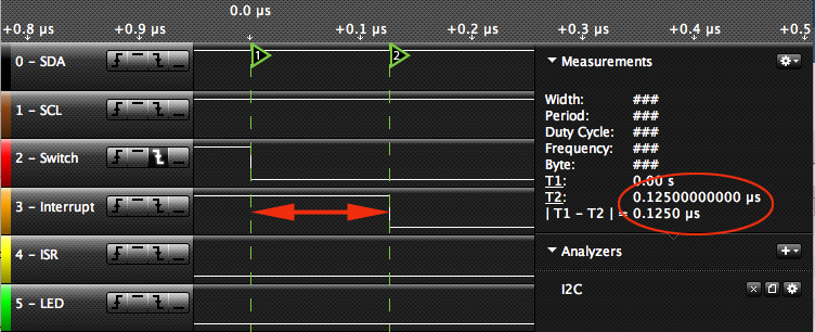


You can clearly see that from the moment the switch was pressed, to when the MCP23017 dropped the interrupt pin to low, was only 0.125 microseconds. That's only 125 nanoseconds! Very fast.

Then we see that only 7 microseconds after the keypress the Arduino interrupt routine also fired (we can tell because of the digitalWrite). So there was a very fast response there, even though it was busy doing something else.


Zooming out to get the bigger picture, we can see that the main loop didn't notice the keypress until an entire second had elapsed. No doubt because I had it beavering away doing this:


  // some important calculations here ...
  for (i = 0; i < 0x7FFFF; i++)
    {}


That is a loop of 524288 iterations, supposed to simulate the processor being busy (eg. updating your LCD screen).

You can also see another batch of switch bounces, circled. That switch certainly had a field day of it. That's 100 ms (1/10 of a second) after it was pressed! In fact, it looks like the second lot of bounces was when I released the switch. That would be right, because when it was released it would have jittered back and forwards a bit until settling down.
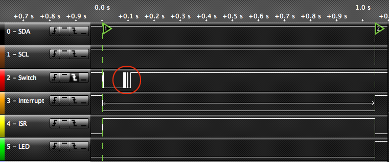


Once the main loop noticed the keypress it calls handleKeypress to find out what it was.


This does the following:

  • Drop the "ISR" pin (point "A") and sets the keyPressed flag back to false, so we can detect a future keypress.
  • For each port, reads from the MCP23017's "interrupt flag" register. This is so we know if this register was responsible for the interrupt or not. If we don't do this we may get an old value from a previous interrupt. These reads are not shown in the logic analyzer capture as I added them later on.
  • Then, for each port, if required, read from the MCP23017's "interrupt capture" register. The purpose of this register is to remember the state of the pins the moment the interrupt occurred, even if they have changed since then. This is just as well, because you can see that by the time we noticed the keypress the key had been released again. Notice that we read 0x01 which shows that the switch on pin 1 was closed.

    
      // Read port values, as required. Note that this re-arms the interrupts.
      if (expanderRead (INFTFA))
        {
        keyValue &= 0x00FF;
        keyValue |= expanderRead (INTCAPA) << 8;    // read value at time of interrupt
        }
      if (expanderRead (INFTFB))
        {
        keyValue &= 0xFF00;
        keyValue |= expanderRead (INTCAPB);        // port B is in low-order byte
        }


    [EDIT] Code changed from earlier version to only alter keyValue if you get an interrupt for that "side" (the A side or the B side).
  • The moment that the "interrupt capture" register is read the MCP23017 cancels the interrupt signal (raises it back to 1) at point "B". This effectively re-arms the interrupts for another time.
  • The code then turns on the on-board LED (point "C") thus giving a visual confirmation we noticed the key-press.


Example code


The full code in the test program was:


// Author: Nick Gammon
// Date: 19 February 2011

// Demonstration of an interrupt service routine connected to the MCP23017

#include <Wire.h>

// MCP23017 registers (everything except direction defaults to 0)

#define IODIRA   0x00   // IO direction  (0 = output, 1 = input (Default))
#define IODIRB   0x01
#define IOPOLA   0x02   // IO polarity   (0 = normal, 1 = inverse)
#define IOPOLB   0x03
#define GPINTENA 0x04   // Interrupt on change (0 = disable, 1 = enable)
#define GPINTENB 0x05
#define DEFVALA  0x06   // Default comparison for interrupt on change (interrupts on opposite)
#define DEFVALB  0x07
#define INTCONA  0x08   // Interrupt control (0 = interrupt on change from previous, 1 = interrupt on change from DEFVAL)
#define INTCONB  0x09
#define IOCON    0x0A   // IO Configuration: bank/mirror/seqop/disslw/haen/odr/intpol/notimp
//#define IOCON 0x0B  // same as 0x0A
#define GPPUA    0x0C   // Pull-up resistor (0 = disabled, 1 = enabled)
#define GPPUB    0x0D
#define INFTFA   0x0E   // Interrupt flag (read only) : (0 = no interrupt, 1 = pin caused interrupt)
#define INFTFB   0x0F
#define INTCAPA  0x10   // Interrupt capture (read only) : value of GPIO at time of last interrupt
#define INTCAPB  0x11
#define GPIOA    0x12   // Port value. Write to change, read to obtain value
#define GPIOB    0x13
#define OLLATA   0x14   // Output latch. Write to latch output.
#define OLLATB   0x15


#define port 0x20  // MCP23017 is on I2C port 0x20

#define ISR_INDICATOR 12  // pin 12
#define ONBOARD_LED 13    // pin 13

volatile bool keyPressed;

// set register "reg" on expander to "data"
// for example, IO direction
void expanderWriteBoth (const byte reg, const byte data ) 
{
  Wire.beginTransmission (port);
  Wire.write (reg);
  Wire.write (data);  // port A
  Wire.write (data);  // port B
  Wire.endTransmission ();
} // end of expanderWrite

// read a byte from the expander
unsigned int expanderRead (const byte reg) 
{
  Wire.beginTransmission (port);
  Wire.write (reg);
  Wire.endTransmission ();
  Wire.requestFrom (port, 1);
  return Wire.read();
} // end of expanderRead

// interrupt service routine, called when pin D2 goes from 1 to 0
void keypress ()
{
  digitalWrite (ISR_INDICATOR, HIGH);  // debugging
  keyPressed = true;   // set flag so main loop knows
}  // end of keypress

void setup ()
{
  pinMode (ISR_INDICATOR, OUTPUT);  // for testing (ISR indicator)
  pinMode (ONBOARD_LED, OUTPUT);  // for onboard LED

  Wire.begin ();  
  Serial.begin (115200); 
  Serial.println ("Starting ..."); 

  // expander configuration register
  expanderWriteBoth (IOCON, 0b01100000); // mirror interrupts, disable sequential mode
 
  // enable pull-up on switches
  expanderWriteBoth (GPPUA, 0xFF);   // pull-up resistor for switch - both ports

  // invert polarity
  expanderWriteBoth (IOPOLA, 0xFF);  // invert polarity of signal - both ports
  
  // enable all interrupts
  expanderWriteBoth (GPINTENA, 0xFF); // enable interrupts - both ports
  
  // no interrupt yet
  keyPressed = false;

  // read from interrupt capture ports to clear them
  expanderRead (INTCAPA);
  expanderRead (INTCAPB);
  
  // pin 19 of MCP23017 is plugged into D2 of the Arduino which is interrupt 0
  attachInterrupt(0, keypress, FALLING);
  
}  // end of setup

// time we turned LED on
unsigned long time = 0;
unsigned int keyValue = 0;

// called from main loop when we know we had an interrupt
void handleKeypress ()
{
  
  delay (100);  // de-bounce before we re-enable interrupts
  
  keyPressed = false;  // ready for next time through the interrupt service routine
  digitalWrite (ISR_INDICATOR, LOW);  // debugging
  
  // Read port values, as required. Note that this re-arms the interrupts.
  if (expanderRead (INFTFA))
    {
    keyValue &= 0x00FF;
    keyValue |= expanderRead (INTCAPA) << 8;    // read value at time of interrupt
    }
  if (expanderRead (INFTFB))
    {
    keyValue &= 0xFF00;
    keyValue |= expanderRead (INTCAPB);        // port B is in low-order byte
    }
  
  Serial.println ("Button states");
  Serial.println ("0                   1");
  Serial.println ("0 1 2 3 4 5 6 7 8 9 0 1 2 3 4 5");
  
  // display which buttons were down at the time of the interrupt
  for (byte button = 0; button < 16; button++)
    {
    // this key down?
    if (keyValue & (1 << button))
      Serial.print ("1 ");
    else
      Serial.print (". ");
    
    } // end of for each button

  Serial.println ();
  
  // if a switch is now pressed, turn LED on  (key down event)
  if (keyValue)
    {
    time = millis ();  // remember when
    digitalWrite (ONBOARD_LED, HIGH);  // on-board LED
    }  // end if
  
}  // end of handleKeypress

void loop ()
{
  // was there an interrupt?
  if (keyPressed)
    handleKeypress ();

  // turn LED off after 500 ms 
 if (millis () > (time + 500) && time != 0)
   {
    digitalWrite (ONBOARD_LED, LOW);
    time = 0;
   }  // end if time up
 
}  // end of loop


Conclusion


The example presented shows how you can notice a key-press on up to 16 buttons, even if your code was doing some very CPU-intensive work.

All this is done with a minimal number of wires connected between where the buttons are and the Arduino (ground, +5V, SDA, SCL and the interrupt line).

You could handle more than 16 switches by using more than one MCP23017, see next post.

More information


More information about I2C is here:

http://www.gammon.com.au/forum/?id=10896

My article about hooking up a graphics LCD screen using I2C is here:

http://www.gammon.com.au/forum/?id=10940

Information about keyboard matrices, diodes and ghosting:

http://www.dribin.org/dave/keyboard/one_html/

Microchip's MCP23017 device:

http://www.microchip.com/wwwproducts/Devices.aspx?dDocName=en023499


[EDIT] Amended on 20th February 2011 to test all 16 switches, and have a more sophisticated key-press detection routine. This shows in the serial output which button has been pressed.
Amended on Mon 09 Mar 2015 08:34 PM by Nick Gammon
Australia Forum Administrator #1
Connecting multiple I/O expanders


After a query on the Arduino forum, I dug a bit deeper to see if I could connect more than one MCP23017 chip, to handle over 16 inputs. It turns out this is fairly simple. Changes were:

  • Configure the MCP23017 interrupt ports to be "open drain" which means they get pulled low on an interrupt, but are high-impedance when not on an interrupt. Effectively this means the interrupt ports can be shared.
  • Wired the MCP23017 interrupt pins together (that is connected pin 19 to pin 19).
  • Configured port D2 of the Arduino to have an internal pull-up resistor. This makes sure that D2 is high if neither MCP23017 is showing an interrupt.
  • Connected a second MCP23017, wiring up everything the same as for the first except that address A0 (pin 15) was wired to +5V rather than ground. That made it address 0x21 rather than 0x20, so they had different addresses. Plus connected pin 19 of the second one to pin 19 of the first one, as mentioned above.
  • Modified the code to accept a chip address in the functions expanderRead and expanderWriteBoth.
  • Modified the code to send set-up commands to both chips, and check for interrupts from both chips when the interrupt fired.


This all seems to work reliably, so in principle you should be able to have 64 inputs, by using four MCP23017 chips (for example, the Centipede shield).

Modified code to work with two MCP23017 chips is:


// Author: Nick Gammon
// Date: 20 February 2011

// Demonstration of an interrupt service routine connected to the MCP23017

#include <Wire.h>

// MCP23017 registers (everything except direction defaults to 0)

#define IODIRA   0x00   // IO direction  (0 = output, 1 = input (Default))
#define IODIRB   0x01
#define IOPOLA   0x02   // IO polarity   (0 = normal, 1 = inverse)
#define IOPOLB   0x03
#define GPINTENA 0x04   // Interrupt on change (0 = disable, 1 = enable)
#define GPINTENB 0x05
#define DEFVALA  0x06   // Default comparison for interrupt on change (interrupts on opposite)
#define DEFVALB  0x07
#define INTCONA  0x08   // Interrupt control (0 = interrupt on change from previous, 1 = interrupt on change from DEFVAL)
#define INTCONB  0x09
#define IOCON    0x0A   // IO Configuration: bank/mirror/seqop/disslw/haen/odr/intpol/notimp
//#define IOCON 0x0B  // same as 0x0A
#define GPPUA    0x0C   // Pull-up resistor (0 = disabled, 1 = enabled)
#define GPPUB    0x0D
#define INFTFA   0x0E   // Interrupt flag (read only) : (0 = no interrupt, 1 = pin caused interrupt)
#define INFTFB   0x0F
#define INTCAPA  0x10   // Interrupt capture (read only) : value of GPIO at time of last interrupt
#define INTCAPB  0x11
#define GPIOA    0x12   // Port value. Write to change, read to obtain value
#define GPIOB    0x13
#define OLLATA   0x14   // Output latch. Write to latch output.
#define OLLATB   0x15

#define chip1 0x20  // MCP23017 is on I2C address 0x20
#define chip2 0x21  // MCP23017 is on I2C address 0x21

volatile boolean keyPressed;

// set register "reg" on expander to "data"
// for example, IO direction
void expanderWriteBoth (const byte address, const byte reg, const byte data ) 
{
  Wire.beginTransmission (address);
  Wire.send (reg);
  Wire.send (data);  // port A
  Wire.send (data);  // port B
  Wire.endTransmission ();
} // end of expanderWrite

// read a byte from the expander
unsigned int expanderRead (const byte address, const byte reg) 
{
  Wire.beginTransmission (address);
  Wire.send (reg);
  Wire.endTransmission ();
  Wire.requestFrom (address, (byte) 1);
  return Wire.receive();
} // end of expanderRead

// interrupt service routine, called when pin D2 goes from 1 to 0
void keypress ()
{
  keyPressed = true;   // set flag so main loop knows
}  // end of keypress

void setup ()
{

  Wire.begin ();  
  Serial.begin (9600);  

  // expander configuration register
  expanderWriteBoth (chip1, IOCON, 0b01100100); // mirror interrupts, disable sequential mode, open drain
  expanderWriteBoth (chip2, IOCON, 0b01100100); // mirror interrupts, disable sequential mode, open drain
 
  // enable pull-up on switches
  expanderWriteBoth (chip1, GPPUA, 0xFF);   // pull-up resistor for switch - both ports
  expanderWriteBoth (chip2, GPPUA, 0xFF);   // pull-up resistor for switch - both ports

  // invert polarity
  expanderWriteBoth (chip1, IOPOLA, 0xFF);  // invert polarity of signal - both ports
  expanderWriteBoth (chip2, IOPOLA, 0xFF);  // invert polarity of signal - both ports
  
  // enable all interrupts
  expanderWriteBoth (chip1, GPINTENA, 0xFF); // enable interrupts - both ports
  expanderWriteBoth (chip2, GPINTENA, 0xFF); // enable interrupts - both ports
  
  // no interrupt yet
  keyPressed = false;

  // read from interrupt capture ports to clear them
  expanderRead (chip1, INTCAPA);
  expanderRead (chip2, INTCAPA);
  expanderRead (chip1, INTCAPB);
  expanderRead (chip2, INTCAPB);
  
  // pin 19 of MCP23017 is plugged into D2 of the Arduino which is interrupt 0
  pinMode (2, INPUT);      // make sure input
  digitalWrite (2, HIGH);  // enable pull-up as we have made the interrupt pins open drain
  
  attachInterrupt(0, keypress, FALLING);
  
}  // end of setup

void handleKeypress ()
{
  unsigned int keyValue1 = 0;
  unsigned int keyValue2 = 0;
  
  delay (100);  // de-bounce before we re-enable interrupts

  keyPressed = false;
  
  // check first chip
  if (expanderRead (chip1, INFTFA))
    keyValue1 |= expanderRead (chip1, INTCAPA) << 8;    // read value at time of interrupt
  if (expanderRead (chip1, INFTFB))
    keyValue1 |= expanderRead (chip1, INTCAPB);        // port B is in low-order byte

  // check second chip
  if (expanderRead (chip2, INFTFA))
    keyValue2 |= expanderRead (chip2, INTCAPA) << 8;    // read value at time of interrupt
  if (expanderRead (chip2, INFTFB))
    keyValue2 |= expanderRead (chip2, INTCAPB);        // port B is in low-order byte
  
  // show state of first 16 buttons
  for (byte button = 0; button < 16; button++)
    {
    // this key down?
    if (keyValue1 & (1 << button))
      {
      Serial.print ("Button ");
      Serial.print (button + 1, DEC);
      Serial.println (" now down");
      }  // end of if this bit changed
    
    } // end of for each button
  
  // show state of next 16 buttons
  for (byte button = 0; button < 16; button++)
    {
    // this key down?
    if (keyValue2 & (1 << button))
      {
      Serial.print ("Button ");
      Serial.print (button + 17, DEC);
      Serial.println (" now down");
      }  // end of if this bit changed
    
    } // end of for each button
  
}  // end of handleKeypress

volatile unsigned long i;

void loop ()
{

  // some important calculations here ...
  for (i = 0; i < 0x7FFF; i++)
    {}
  
  // was there an interrupt?
  if (keyPressed)
    handleKeypress ();
 
}  // end of loop


This version doesn't have the debugging stuff in the earlier version. This makes it clearer what is really required to make it work.


Handling multiple button presses


The code above would only detect the first key-press if multiple ones were made in quick succession. If you really need to know that buttons 1 and 2 are held down together, you need to change:


 if (expanderRead (chip1, INFTFA))
    keyValue1 |= expanderRead (chip1, INTCAPA) << 8;    // read value at time of interrupt
  if (expanderRead (chip1, INFTFB))
    keyValue1 |= expanderRead (chip1, INTCAPB);        // port B is in low-order byte

  // check second chip
  if (expanderRead (chip2, INFTFA))
    keyValue2 |= expanderRead (chip2, INTCAPA) << 8;    // read value at time of interrupt
  if (expanderRead (chip2, INFTFB))
    keyValue2 |= expanderRead (chip2, INTCAPB);        // port B is in low-order byte


to:


  keyValue1 |= expanderRead (chip1, GPIOA) << 8;    // read value now
  keyValue1 |= expanderRead (chip1, GPIOB);         // port B is in low-order byte

  // check second chip
  keyValue2 |= expanderRead (chip2, GPIOA) << 8;    // read value now
  keyValue2 |= expanderRead (chip2, GPIOB);         // port B is in low-order byte


That reads the current value rather than the value at the time of the interrupt. Thus you would find what buttons are currently being held down. Of course, you need to react to the interrupt rather quickly in this case, or they may have let go of the button.
Amended on Sun 20 Feb 2011 08:03 PM by Nick Gammon
#2
Hello,
thanks a lot for sharing those informations! Great work and help me a lot! I've realized the hardware and used the software you created and worked immediately. I just noticed that if I press 8 or more push button in the same time arduino will totally freeze and have to hardware reset. Any ideas?
Australia Forum Administrator #3
Probably whatever it is you do when 8 buttons are pushed is the reason (for example, are you lighting LEDs?).

Each output port has a recommended current drain of 20 mA, and an absolute maximum of 40 mA. Plus there are limits for the whole device (200 mA from memory).

So if you have 8 LEDs, all drawing 30 mA (depending on your current limiting resistors) then that is within range for one port, but 8 x 30 is 240 mA which is too high. That might cause the processor to reset.
Amended on Thu 18 Aug 2011 09:59 PM by Nick Gammon
#4
thanks for response!
I have no leds, just the switches!
Australia Forum Administrator #5
How are they wired up?
#6
hello Nick,
sorry delay but my internet connection was unavailable.
I have connected 16 switches, one for any port, with ground in the other side. I have followed your schematics as it is!
For soft, I'musing the first one in this page since I have only one chip.
Australia Forum Administrator #7
I can't reproduce that. I hooked up my board again, and running a wire to each of the 16 pins to ground (one by one) I eventually got this:


Button 1 now down
Button 2 now down
Button 3 now down
Button 4 now down
Button 5 now down
Button 6 now down
Button 7 now down
Button 8 now down
Button 9 now down
Button 10 now down
Button 11 now down
Button 12 now down
Button 13 now down
Button 14 now down
Button 15 now down
Button 16 now down


There was no reset of the processor.

I had to change this:


// Read port values, as required. Note that this re-arms the interrupts.
  if (expanderRead (INFTFA))
    keyValue |= expanderRead (INTCAPA) << 8;    // read value at time of interrupt
  if (expanderRead (INFTFB))
    keyValue |= expanderRead (INTCAPB);        // port B is in low-order byte


to this:


 // Read port values, as required. Note that this re-arms the interrupts.
  if (expanderRead (INFTFA) || expanderRead (INFTFB))
    {
    keyValue |= expanderRead (INTCAPA) << 8;    // read value at time of interrupt
    keyValue |= expanderRead (INTCAPB);        // port B is in low-order byte
    }


Otherwise it didn't report the "B" buttons as being down if you connected on of the "A" buttons (because only the "A" button had the interrupt).

So if it isn't working maybe it is something electrical?
Amended on Tue 23 Aug 2011 01:39 AM by Nick Gammon
#8
Nick,
thanks a lot for your efforts! I have checked carefully the schematics and my breadboard and looks ok. I have measured power supply before and after the freeze and it's always around 5.04V (I'm using an external stabilized power supply, a switching module from ALPS).
The only differences is that I'm using pin 3 and interrupt 1 on the arduino 2009 instead of pin 2 and interrupt 0.
I've also included some decoupling capacitor (1x10uF and one 100nF very close the mcp chip supply pin).
Today I've tried to use the open drain command on mcp and pullup pin3 and results was much promises since it worked at my efforts to freeze it for several times but at the end it just stop working.
Pressing, one, two, three buttons in the same time will always work perfectly, pressing a bunch of push buttons 7 or more in the same time now sometims result in a complete freeze of the arduino.
At this point I'm think that something wrong with the arduino 2009 clone I'm using or the mcp chip is defective!

What I have not clearly understand is why you reset the internal interrupt of the mcp chip and don't just use the arduino interrupt to detect when chip goes low (as happen in ntx pcf8574 chips)
Thanks a lot for response and your time!
Australia Forum Administrator #9
Quote:

The only differences is that I'm using pin 3 and interrupt 1 on the arduino 2009 instead of pin 2 and interrupt 0.


Why? Is there more to this than exactly reproducing my circuit and code? Perhaps post your complete code in that case.

The capacitors are a good idea, won't do any harm.

Quote:

I have not clearly understand is why you reset the internal interrupt of the mcp chip and don't just use the arduino interrupt to detect when chip goes low ...


I do use the Arduino interrupt. The MCP23017 generates an interrupt on a pin change of any of the 16 ports. That interrupt is then detected by the Arduino. That interrupt tells it to enquire (via I2C) about the status of the pins.
#10
Thanks Nick! I prolly finally found the problem and of course was my mistake. I've connected the interrupt pin 20 instead of 19 of the mcp! Unfortunatly I'm in vacation so I don't have a solder here to change the wire so I cannot verify if it's working.
There's a way to redirect MCP interrupts to this pin via software?

I cannot resist to bring my arduino clone in vacation so I've builded up a board with an Graphic LCD connected to a MCP23017 with your code (and working beautiful) and another MCP23017 with different address connected to 16 switches and a arduino clone board inserted in the board for study purposes.

Unfortunatly I cannot use interrupt 0 on arduino since the pin has not a stable connection so I changed these lines in your code:

pinMode (3, INPUT);      // make sure input
digitalWrite (3, HIGH);  // enable pull-up
  
attachInterrupt(1, keypress, FALLING);

Apart the interrupt changes on arduino and MCP (that was clearly my mistake) I followed your schematic as on graphic LCD (that as I told before works beautifully, just changed the mcp address on this last one)
Australia Forum Administrator #11
Greete said:

There's a way to redirect MCP interrupts to this pin via software?


I had "mirror interrupts" turned on, which according to the datasheet "the INT pins are internally connected".

So, either pin 19 or 20 should work.
#12
I've made some other researches, I've Saleae Logic analyzer with me (same as yours I think), I've connected sda/scl and interrupt, played with buttons and when I pushed all together the interrupt goes low and remains low constantly so looks like it's mcp chip the problem. I'm not a big expert of the logic analyzer but I was able to correctly assign sda and scl to the saleae I2C analyzer module and I saved the session with data, so if you want take a look... .)

http://depositfiles.com/files/c2uz01lhd
Amended on Sat 27 Aug 2011 07:57 PM by Greete
Australia Forum Administrator #13
Can't you just post the image on an image hosting site? I had to wait 60 seconds and then got a .rar file which I can't unzip on the Mac I am sitting at right now.

[EDIT] Also a couple of extra advertisement pages opened in my web browser, which is quite annoying.

Anyway, without seeing the image, the interrupt line will go low on an interrupt and stay low until you "tell" the chip you have seen the interrupt by reading from the appropriate ports. In the setup phase I did it like this:


// read from interrupt capture ports to clear them
  expanderRead (INTCAPA);
  expanderRead (INTCAPB);


and later on, during operation:


// Read port values, as required. Note that this re-arms the interrupts.
  if (expanderRead (INFTFA) || expanderRead (INFTFB))
    {
    keyValue |= expanderRead (INTCAPA) << 8;    // read value at time of interrupt
    keyValue |= expanderRead (INTCAPB);        // port B is in low-order byte
    }


Reading INTCAPA and INTCAPB is when the interrupts should be cleared. You could set a debugging digital line high (eg. D7) just before doing that and then low afterwards. Then check those lines with the logic analyzer and see if the interrupt line is changing in that interval.

I would be a bit surprised if you have a faulty chip. Many times these things come down to software problems.
Amended on Sat 27 Aug 2011 09:25 PM by Nick Gammon
#14
I got it!
dunno exact the reason and the solution is far from being ok but like this it works! I have added some extra check to verify if the interrupt is firing the arduino pin.


void handleKeypress ()
{
  int checkInterrupt = 0;// ADDEDD
  checkInterrupt = digitalRead(2);// ADDEDD
  if (checkInterrupt == LOW){// ADDEDD
    unsigned int keyValue1 = 0;
    delay (100);  // de-bounce before we re-enable interrupts
    keyPressed = false;
    // check first chip
    while(checkInterrupt == LOW){// ADDEDD
    checkInterrupt = digitalRead(2);// ADDEDD
      if (expanderRead (chip1, INFTFA))
        keyValue1 |= expanderRead (chip1, INTCAPA) << 8;    // read value at time of interrupt
      if (expanderRead (chip1, INFTFB))
        keyValue1 |= expanderRead (chip1, INTCAPB);        // port B is in low-order byte
    }
      // show state of first 16 buttons
      for (byte button = 0; button < 16; button++)
      {
        // this key down?
        if (keyValue1 & (1 << button))
        {
          Serial.print ("Button ");
          Serial.print (button + 1, DEC);
          Serial.println (" now down");
        }  // end of if this bit changed

      } // end of for each button
    
  }
}  // end of handleKeypress


As I tell, dunno why but no more freezes!

In the initialize section I added these lines but I dunno if necessary:

  expanderWrite (chip1,IODIRB,B11111111); //port B = INPUT
  expanderWrite (chip1,IODIRA,B11111111); //port A = INPUT


Sorry for my last post!

If you still need I can post the saleae session zipped in my site (that can be opened by mac)

[EDIT] I have changed the while loop because in the last mod it was returning 2 times the button value, now it's okey
Amended on Sat 27 Aug 2011 10:02 PM by Greete
Australia Forum Administrator #15
The chips defaults to all lines input.

You shouldn't need that extra code. If you are in handleKeypress then it should only be because the interrupt fired ... unless you have changed other things around.

Quote:

The only differences is that I'm using pin 3 and interrupt 1 on the arduino 2009 instead of pin 2 and interrupt 0.


So why are you testing pin 2 in your changes?
#16
Hi Nick!
this morning I got a solder and changed pin 19 and soldered a wire to pin 2 to bypass the problem with the connector so now I'm using exact your hardware setup.
For software I'm using your second code and deleted any reference to chip2 (I'm using just one chip).
This further modification will fix the problem and uses less code:

    while(digitalRead(2) == LOW){// ADDEDD
      if (expanderRead (chip1, INFTFA))
        keyValue1 |= expanderRead (chip1, INTCAPA) << 8;    // read value at time of interrupt
      if (expanderRead (chip1, INFTFB))
        keyValue1 |= expanderRead (chip1, INTCAPB);        // port B is in low-order byte
    }


Strangely, even this one!

     keyValue1 |= expanderRead (chip1, INTCAPA) << 8;    // read value at time of interrupt
      if (expanderRead (chip1, INFTFB))
     keyValue1 |= expanderRead (chip1, INTCAPB);        // port B is in low-order byte 
// ADDED, attemp to reset the interrupt again
expanderRead (chip1, INTCAPA)
expanderRead (chip1, INTCAPB);


Looks like I have to reset MCP interrupt 2 times!
Amended on Sat 27 Aug 2011 10:19 PM by Greete
Australia Forum Administrator #17
Hmm, strange.

You shouldn't need the while loop.

However I admit I tested with the B port initially and not the A one.
#18
I've made a simple experiment. I have added a parameter for check when the while loop is necessary.

    int count = 0;//just for test
    while(digitalRead(2) == LOW){// ADDEDD
      Serial.print ("count: ");//just for test
      Serial.println (count);//just for test
      if (expanderRead (chip1, INFTFA))
        keyValue1 |= expanderRead (chip1, INTCAPA) << 8;// read value at time of interrupt
      if (expanderRead (chip1, INFTFB))
        keyValue1 |= expanderRead (chip1, INTCAPB); // port B is in low-order byte
      count++;//just for test
    }


Most of the time I just get count: 0 but pressing many buttons at the same time will increase the count to 1 or 2!
Amended on Wed 31 Aug 2011 10:19 PM by Greete
Australia Forum Administrator #19
Try the amendment I suggested:


// Read port values, as required. Note that this re-arms the interrupts.
  if (expanderRead (INFTFA) || expanderRead (INFTFB))
    {
    keyValue |= expanderRead (INTCAPA) << 8;    // read value at time of interrupt
    keyValue |= expanderRead (INTCAPB);        // port B is in low-order byte
    }


#20
Hi Nick!
I have try the amendment you suggested but still have the freeze.
At this time the only way to avoid the freeze is the while loop, must be some timing problem of the mcp chip.
Notice that in normal situation nobody will press all those buttons but I'm trying to build a toy for my son of 4 years old so...

[edit]
the only difference with this code is I'm able to press 2 buttons in the same time but only if one is in the bank a and the other is in b.
The other code let me press just one button at time.
Amended on Fri 02 Sep 2011 10:08 AM by Greete
#21
Hi Nick!
Always a big pleasure visit your site, it's always full of useful informations!

I'm trying to use your code for the MCP23017 for the SPI version of the same chip, the MCP23S17. Reading your notes about SPI I have modified like the following to use both chip for experiments:

#include <SPI.h>
#include "pins_arduino.h"

// Author: Nick Gammon
// Date: 20 February 2011

// Demonstration of an interrupt service routine connected to the MCP23017

#include <Wire.h>

// MCP23017 registers (everything except direction defaults to 0)
#define SS   53 //I'm using arduinoMega2560
#define IODIRA   0x00   // IO direction  (0 = output, 1 = input (Default))
#define IODIRB   0x01
#define IOPOLA   0x02   // IO polarity   (0 = normal, 1 = inverse)
#define IOPOLB   0x03
#define GPINTENA 0x04   // Interrupt on change (0 = disable, 1 = enable)
#define GPINTENB 0x05
#define DEFVALA  0x06   // Default comparison for interrupt on change (interrupts on opposite)
#define DEFVALB  0x07
#define INTCONA  0x08   // Interrupt control (0 = interrupt on change from previous, 1 = interrupt on change from DEFVAL)
#define INTCONB  0x09
#define IOCON    0x0A   // IO Configuration: bank/mirror/seqop/disslw/haen/odr/intpol/notimp
//#define IOCON 0x0B  // same as 0x0A
#define GPPUA    0x0C   // Pull-up resistor (0 = disabled, 1 = enabled)
#define GPPUB    0x0D
#define INFTFA   0x0E   // Interrupt flag (read only) : (0 = no interrupt, 1 = pin caused interrupt)
#define INFTFB   0x0F
#define INTCAPA  0x10   // Interrupt capture (read only) : value of GPIO at time of last interrupt
#define INTCAPB  0x11
#define GPIOA    0x12   // Port value. Write to change, read to obtain value
#define GPIOB    0x13
#define OLLATA   0x14   // Output latch. Write to latch output.
#define OLLATB   0x15

#define chip1 0x20  // MCP23017 is on I2C address 0x20


volatile boolean keyPressed;

// set register "reg" on expander to "data"
// for example, IO direction
void expanderWriteBoth (const byte address, const byte reg, const byte data ) 
{
  if (SS>0){
    digitalWrite(SS, LOW);
    SPI.transfer (reg);
    SPI.transfer (data);
    SPI.transfer (data);
    digitalWrite(SS, HIGH);
  } 
  else {
    Wire.beginTransmission (address);
    Wire.send (reg);
    Wire.send (data);  // port A
    Wire.send (data);  // port B
    Wire.endTransmission ();
  }
} // end of expanderWrite

// read a byte from the expander
unsigned int expanderRead (const byte address, const byte reg) 
{
  unsigned int data = 0;
  if (SS>0){
    digitalWrite(SS, LOW);
    SPI.transfer (reg);
    digitalWrite(SS, HIGH);
    digitalWrite(SS, LOW);
    data = SPI.transfer (0);
    digitalWrite(SS, HIGH);
  } 
  else {
    Wire.beginTransmission (address);
    Wire.send (reg);
    Wire.endTransmission ();
    Wire.requestFrom (address, (byte) 1);
    data = Wire.receive();
  }
  return data;
} // end of expanderRead

// interrupt service routine, called when pin D2 goes from 1 to 0
void keypress ()
{
  keyPressed = true;   // set flag so main loop knows
}  // end of keypress

void setup ()
{
  Serial.begin (38400); 
  if (SS>0){
    SPI.begin ();
    SPI.setClockDivider(SPI_CLOCK_DIV8);
    digitalWrite(SS, HIGH);
  } 
  else {
    Wire.begin ();
  }

  // expander configuration register
  expanderWriteBoth (chip1, IOCON, 0b01100100); // mirror interrupts, disable sequential mode, open drain

  // enable pull-up on switches
  expanderWriteBoth (chip1, GPPUA, 0xFF);   // pull-up resistor for switch - both ports

  // invert polarity
  expanderWriteBoth (chip1, IOPOLA, 0xFF);  // invert polarity of signal - both ports
 
  // enable all interrupts
  expanderWriteBoth (chip1, GPINTENA, 0xFF); // enable interrupts - both ports
 
  // no interrupt yet
  keyPressed = false;

  // read from interrupt capture ports to clear them
  expanderRead (chip1, INTCAPA);
  expanderRead (chip1, INTCAPB);

  // pin 19 of MCP23017 is plugged into D18 of the ArduinoMega which is interrupt 5
  pinMode (18, INPUT);      // make sure input
  digitalWrite (18, HIGH);  // enable pull-up as we have made the interrupt pins open drain

  attachInterrupt(5, keypress, FALLING);

}  // end of setup

void handleKeypress ()
{
  unsigned int keyValue1 = 0;

  delay (100);  // de-bounce before we re-enable interrupts

  keyPressed = false;

  // check first chip
  if (expanderRead (chip1, INFTFA))
    keyValue1 |= expanderRead (chip1, INTCAPA) << 8;    // read value at time of interrupt
  if (expanderRead (chip1, INFTFB))
    keyValue1 |= expanderRead (chip1, INTCAPB);        // port B is in low-order byte

  // show state of first 16 buttons
  for (byte button = 0; button < 16; button++)
  {
    // this key down?
    if (keyValue1 & (1 << button))
    {
      Serial.print ("Button ");
      Serial.print (button + 1, DEC);
      Serial.println (" now down");
    }  // end of if this bit changed

  } // end of for each button

}  // end of handleKeypress

volatile unsigned long i;

void loop ()
{

  // some important calculations here ...


  // was there an interrupt?
  if (keyPressed)
    handleKeypress ();

}  // end of loop


The I2C version works but the SPI not. I've changed some pin since I'm using an Mega2560 but I'm suspect that the SPI routine that read data is not correct, can you help me?
Amended on Tue 10 Jan 2012 04:04 PM by Greete
Australia Forum Administrator #22
Here:


    digitalWrite(SS, LOW);
    SPI.transfer (reg);
    digitalWrite(SS, HIGH);
    digitalWrite(SS, LOW);
    data = SPI.transfer (0);
    digitalWrite(SS, HIGH);


I wouldn't raise SS during a "transaction". Try:


    digitalWrite(SS, LOW);
    SPI.transfer (reg);
    data = SPI.transfer (0);
    digitalWrite(SS, HIGH);
#23
Thanks Nick!
Unfortunatly nothing works. I've added Serial.print ("Int Triggered!!!"); to keypress function. Pressing button has no result so it looks like the chip has not been correctly configured. I'll try to change chip and use an arduino uno, just to be sure that is not an hardware problem...
#24
Hi Nick,

I have found your MCP23017 code most useful for a system I have been setting up. I am new to Arduino and the MCP23017 but have got a lot more from the centipede shield with your code than from the samples provided with the shield.

I hope you might help me understand one last issue I have with MCP chip features.

I had been recommended the chip for its ability to store pin status at the time of the interrupt. What I really need, and am now doubting is a capability, is to store multiple input pin states without reading the ports between inputs. Reading the databook again I am not sure that pin states continue to be stored if the interrupt is not cleared.

The implication was that I could get quick timing data from interrupts generated by the chip and read the ports later to find out with pin(s) had generated the interrupt.

The multiple inputs are caused by a ball projectile passing a photosensor array to start/stop a timer. I need to know where the centre of the ball passes the array and would need to know the 5 sensors its profile triggered to approximate. I only need to start the timer with the first sensor picked up by the mcp.

Do you see anyway to do this without extra hardware?

Any pointers would be most appreciated.

Kind regards,

Rossco

Australia Forum Administrator #25
Rossco said:

Reading the databook again I am not sure that pin states continue to be stored if the interrupt is not cleared.


The datasheet seems to say it copies the first state (current state). This is useful because by the time you service the interrupt the state might have changed.

The only solution I can think of is to handle the interrupt fast enough to get the readings from the "real" port (not the saved one). So the front of the ball triggers the interrupt, and then you read the other ones.

However assuming the front of the ball hits the sensor first, doesn't that tell you where the ball is?
#26
Thanks for the reply. That clarifies that the MCP doesn't work quite the way I had hoped.

I just need to try this in practice I think. I get the stuff back next week. What you propose should work in theory; the the sensor triggering the interrupt is always the one at the centre of the ball and therefore I don't need the other readings. However, in doing this I must assume the arduino will never miss the first trigger. The aim is accuracy of 0.5 m/s which relates to mm and ms resolution - if budget were not an issue the arduino would not be the first choice.

In reality the arduino may well be fast and reliable enough to read and clear the interrupt state within the ISR and still catch the leading edge of the ball every time.

Thanks again Nick, great site.

Ross
#27
Hi Nick,

I now have the ball measurement system close to working. As your logic analyser showed, the mcp reacts very quickly, so I am for now assuming the bit set in INTCAP is first sensor to be triggered by the leading edge of the ball.

When I read the results from INTCAP following one pass of the ball through the rig, the values seem to match up. However, on the next pass the INTCAP values seem to retain the previous values as well as new ones. At the moment the only way to clear INTCAP is force a hard reset of the MCP by disconnecting power.

Can you see any reason why this would happen? reading INTCAP clears the interrupt as the datasheet states, but for some reason INTCAP maintians high bits GPIOs that were not triggered. Do I need to read INTFA/B as well to ensure the INTCAP values are true each time?

I have ensured all programme variables are cleared, so it does seem to be INTCAP itself causing the problem.

Many thanks,

Rossco
Australia Forum Administrator #28
The datasheet says INTCAP is cleared by reading from it, but why not just check INTF? That tells you which pins caused an interrupt, and INTCAP tells you the state at the time of the interrupt.
#29
Hi Nick,

Working on our MCP system sporadically, but think we are progressively closer to a fully functioning system. Your suggestion to use INTF instead of INTCAP seemed to do the trick in our simultations. However, we are still having some issues with the MCP registers when testing with a real ball.

When we hook up our reversed biased photodiode divder circuits (no amplifier, output taken across a single resistor) to a DAQ we are measuring expected results for the sensor outputs when a ball passes. They at least working on a comercially developed unit.

When we simulate 5 simultaneous inputs to the MCP using an arduino as a pulse generator (pull down resistors used for uconnected GPIOS), INTF/INTCAP indentify the correct triggers. However when we hook up the diode sensors to the MCP chips we get funny and unexpected results from INTF e.g. bits set are not adjacent and do not represent the ball diameter and what we are reading on the DAQ. It seems there are mis triggers.

The ball is fired at around 30 m/s through the sensor arrays. Sensors are therefore triggered for roughly 30 ms, with a slight delay between each pulse as dictatated by the ball edge profile. I wouldn't have thought this would be a problem for the MCP given the 125 ns response. Do think ground bounce or other crosstalk/noise could be the issue here? Any other ideas of what to try?

Microchip have suggested that increasing I2C speed may help. We have tried this without success, but I would have thought lower speeds would be less problematic.

Thanks,

Ross
Australia Forum Administrator #30
Without seeing more details (like code) it is hard to say. The device may respond in 125 nS but handling an interrupt on the processor is more likely to take around 5 uS from start to finish. Plus it depends what you are doing in the ISR.
Amended on Mon 03 Sep 2012 11:52 PM by Nick Gammon
#31
Hi,

I don't think the interrupt has any impact on the MCP chips as the INT registers are not read/cleared until all the time critical interrupts have occured. With th eball travelling approximately 30 m/s and travelling 400 mm between sensor arrays there is about 13000 ms between interrupt triggers at the arduino input.

The interrupt code is:

//Interrupt Service Routine Code for Timer1 Input Capture
ISR(TIMER1_CAPT_vect){
  if( bit_is_set(TCCR1B ,ICES1)){ // was first was rising edge detected ?
    TCNT1 = 0; // reset the counter
  }
  else if((! bit_is_set(TCCR1B ,ICES1)) && (EdgeCount==1)){ // was first falling edge detected ?
    time1=ICR1; // record time between 1st and 2nd array
  }
  else if((! bit_is_set(TCCR1B ,ICES1)) && (EdgeCount==3)){ // was second falling edge detected ?
    time2=ICR1; // record time between 2nd and 3rd array
  }
++EdgeCount;
TCCR1B ^= _BV(ICES1); // toggle bit value to trigger on the other edge
}


The main loop waits until the ball has passed all 4 sensor arrays and then reads the INTF values from each chip. as stated in my previous post, the results do not match those expected. Any ideas?

the EdgeCount and time variables in the interrupt routine are volatile and read with interrupts turned off (in functions edge_count() and final_timex, rather than main loop) as I believe is standard practice.


if(edge_count() >= NUMBER_EDGES ){
  
  //these next defintions are made in the main loop rather than programme start as the should be cleared after each ball pass

  volatile unsigned int time1ms =0; //time registers store time values in microseconds and seconds for display and calculation
  volatile float time1s =0.0;
  volatile unsigned int time2ms=0;
  volatile float time2s=0.0;

  volatile unsigned int time1b;
  volatile unsigned int time2b;
  
  time1b=final_time1();
  time2b=final_time2();
  time1ms = time1b / 2;
  time1s= (float)time1ms / 1000000.0;
  time2ms= time2b / 2;
  time2s= (float)time2ms / 1000000.0;

  //These statements read the 8 bit INTA and INTB registers of each MCP23017 chip and combine and store these registers a 16bit vlaues
  chip1intA=expanderRead(chip1, INFTFA);
  chip1intB=expanderRead(chip1, INFTFB);
    chip1profile= (chip1intB << 8 | chip1intA); // this statement shifts the intB binary byte 8 bits to the left and combines it with the intA byte through OR logic to create a single 16 bit value.
  chip2intA=expanderRead(chip2, INFTFA);
  chip2intB=expanderRead(chip2, INFTFB);
    chip2profile= chip2intB << 8 | chip2intA;
  chip3intA=expanderRead(chip3, INFTFA);
  chip3intB=expanderRead(chip3, INFTFB);
    chip3profile= chip3intB << 8 | chip3intA;
  chip4intA=expanderRead(chip4, INFTFA);
  chip4intB=expanderRead(chip4, INFTFB);
    chip4profile= chip4intB << 8 | chip4intA;
  chip5intA=expanderRead(chip5, INFTFA);
  chip5intB=expanderRead(chip5, INFTFB);
    chip5profile= chip5intB << 8 | chip5intA;
  chip6intA=expanderRead(chip6, INFTFA);
  chip6intB=expanderRead(chip6, INFTFB);
    chip6profile= chip6intB << 8 | chip6intA;
    
array1profile = ((long)chip2profile << 16) | chip1profile;
array2profile = ((long)chip4profile << 16) | chip3profile;
    
Australia Forum Administrator #32


if(edge_count() >= NUMBER_EDGES ){
  
...

  volatile float time1s =0.0;
  volatile unsigned int time2ms=0;
  volatile float time2s=0.0;

  volatile unsigned int time1b;
  volatile unsigned int time2b;


I don't see the point of putting volatile variables here. Why are you doing that?
#33
Hello Nick,
I finally solved to use your code for the MCP23S17 version.
I simply forget to address the chip!!!
Here's the working code if someone need it

UPDATE
For some unknow reason the MCP23s17 not works as his 23017 brother! The following code works with both chip but SPI version will drop the INT to LOW after some time (leave alone 3 min, press any button and...bang!), causing a freeze of the chip (that sometimes needs to force resetted!
I spent an entire week study the phenomena and tried at list 4 different libraries and this happened always (change chip won't help, tried 10 different ones and 3 processors).
If someone has any idea would be great!


#include <SPI.h>
#include "pins_arduino.h"

// Author: Nick Gammon
// Date: 20 February 2011

// Demonstration of an interrupt service routine connected to the MCP23017
// modded by Aleandro Greete for use with MCP23S17 (SPI version)

#include <Wire.h>

#define IODIRA   0x00   // IO direction  (0 = output, 1 = input (Default))
#define IODIRB   0x01
#define IOPOLA   0x02   // IO polarity   (0 = normal, 1 = inverse)
#define IOPOLB   0x03
#define GPINTENA 0x04   // Interrupt on change (0 = disable, 1 = enable)
#define GPINTENB 0x05
#define DEFVALA  0x06   // Default comparison for interrupt on change (interrupts on opposite)
#define DEFVALB  0x07
#define INTCONA  0x08   // Interrupt control (0 = interrupt on change from previous, 1 = interrupt on change from DEFVAL)
#define INTCONB  0x09
#define IOCON    0x0A   // IO Configuration: bank/mirror/seqop/disslw/haen/odr/intpol/notimp
//#define IOCON 0x0B  // same as 0x0A
#define GPPUA    0x0C   // Pull-up resistor (0 = disabled, 1 = enabled)
#define GPPUB    0x0D
#define INFTFA   0x0E   // Interrupt flag (read only) : (0 = no interrupt, 1 = pin caused interrupt)
#define INFTFB   0x0F
#define INTCAPA  0x10   // Interrupt capture (read only) : value of GPIO at time of last interrupt
#define INTCAPB  0x11
#define GPIOA    0x12   // Port value. Write to change, read to obtain value
#define GPIOB    0x13
#define OLLATA   0x14   // Output latch. Write to latch output.
#define OLLATB   0x15

#define SS   4  //I'm using ATMEGA 640P
#define chip1 0x25  // MCP23017 is on I2C address 0x25
#define INTused 0 
#define INTpin 10 //I'm using ATMEGA 640P, this pin has INT0 hardwired

volatile boolean keyPressed;

void expanderWriteBoth (const byte address, const byte reg, const byte data ) 
{
  if (SS > 0){
    digitalWrite(SS, LOW);
    SPI.transfer (address << 1);//this was missed!
    SPI.transfer (reg);
    SPI.transfer (data);
    SPI.transfer (data);
    digitalWrite(SS, HIGH);
  } 
  else {
    Wire.beginTransmission (address);
    Wire.write (reg);
    Wire.write (data);  // port A
    Wire.write (data);  // port B
    Wire.endTransmission ();
  }
}

unsigned int expanderRead (const byte address, const byte reg) 
{
  unsigned int data = 0;
  if (SS > 0){
    digitalWrite(SS, LOW);
    SPI.transfer ((address << 1) | 1);//this was missed!
    SPI.transfer (reg);
    data = SPI.transfer(0);
    digitalWrite(SS, HIGH);
  } 
  else {
    Wire.beginTransmission (address);
    Wire.write (reg);
    Wire.endTransmission ();
    Wire.requestFrom (address, (byte) 1);
    data = Wire.read();
  }
  return data;
}

void keypress ()
{
  keyPressed = true;   // set flag so main loop knows
}

void setup ()
{
  Serial.begin (38400); 
  if (SS > 0){
    SPI.begin ();
    SPI.setClockDivider(SPI_CLOCK_DIV8);
    digitalWrite(SS, HIGH);
  } 
  else {
    Wire.begin ();
  }

  // expander configuration register
  expanderWriteBoth (chip1, IOCON, 0b01100100); // mirror interrupts, disable sequential mode, open drain
  // enable pull-up on switches
  expanderWriteBoth (chip1, GPPUA, 0xFF);   // pull-up resistor for switch - both ports
  // invert polarity
  expanderWriteBoth (chip1, IOPOLA, 0xFF);  // invert polarity of signal - both ports
  // enable all interrupts
  expanderWriteBoth (chip1, GPINTENA, 0xFF); // enable interrupts - both ports

  keyPressed = false;

  // read from interrupt capture ports to clear them
  expanderRead (chip1, INTCAPA);
  expanderRead (chip1, INTCAPB);

  pinMode (INTpin, INPUT);      // make sure input
  digitalWrite (10, HIGH);  // enable pull-up as we have made the interrupt pins open drain

  attachInterrupt(INTused, keypress, FALLING);

} 

void handleKeypress ()
{
  detachInterrupt(INTused);//protect from further interrupts 
  unsigned int keyValue1 = 0;
  delay (30);  // de-bounce before we re-enable interrupts
  if (expanderRead (chip1, INFTFA))
    keyValue1 |= expanderRead (chip1, INTCAPA);
  if (expanderRead (chip1, INFTFB))
    keyValue1 |= expanderRead (chip1, INTCAPB) << 8;        
  // show state of first 16 buttons
  for (byte button = 0; button < 16; button++)
  {
    // this key down?
    if (keyValue1 & (1 << button))
    {
      Serial.print ("Button ");
      Serial.print (button + 1, DEC);
      Serial.println (" now down");
    }  // end of if this bit changed

  }
  keyPressed = false;
  attachInterrupt(INTused, keypress, FALLING);
} 

void loop ()
{

  // was there an interrupt?
  if (keyPressed)
    handleKeypress ();

}  // end of loop


I also added a detachInterrupt to protect the routine that read buttons from any further interrupts.
Thanks again for your lessons, I definetively learn more from this pages than arduino forum!
Amended on Mon 29 Oct 2012 01:17 AM by Greete
#34
Here's a version that uses Squential Operation Mode bit enabled. This seems to solve the problem I had in the past that simetimes the interrupt flag has not been correctly reset (read my old posts in this section).
Btw I experimented a lot with this chip and his SPI brother 23s17 and results are that interrupt section it's not working always as expected. For example, mcp23s17 configured in input for use the interrupts will always freeze down the INT port after some minute (checked with at list 10 different chips, various configuration and even different libraries), use it with no INT option will not cause any problem (looks like that only INT output pin it's affected).
In out mode it works always perfect, just find some difficulties when different chips use the HAEN option and share the same CS pin (better send HAEN to all chips before all).
The I2C version works (in input configuration) much better but find that Sequential Mode it's more reliable (at list as input with INT option). In out mode works as expect always (since no HAEN mode for this chip).
I find useful use a small button tied to ground engage hardware reset for this chips during configuration experiments since sometimes they just freeze up and works strangely, this just for experiments, not needed for applications.

Here's the code for use with Squential Operation mode bit
Thanks again for your lessons, Nick, it's always a great inspiration see your pages.

#include <Wire.h>
/*
Ths version has been modified for use with Squential Operation mode bit
This use slight less code
*/
#define I2C_SW1 0x27//USE THE CORRECT ADDRESS! this is 3 10k resistors tied to +
/* Multiple Interrupt defs and pins */
#define INT_DEBOUNCE_TIME 40
#define INT_COMMON_PIN 10
#define INT_COMMON_NUM 0
#define IODIR 0x00
#define IOPOL 0x02
#define GPINTEN 0x04
#define DEFVAL  0x06
#define INTCON  0x08
#define IOCON    0x0A   // IO Configuration: bank/mirror/seqop/disslw/haen/odr/intpol/notimp
#define GPPU  0x0C
#define INFTF  0x0E
#define INTCAP  0x10
#define GPIO  0x12
#define OLLAT  0x14

volatile byte keyPressed;

void setup(void)
{
#if defined DBG
  Serial.begin(38400);
  Serial.println("inited");
#endif
  Wire.begin(); // start I2C
  TWBR = ((F_CPU / 400000L) - 16) / 2;//I2C a 400Khz
  //-------------------------> SWITCH LOGIC CONFIGURATION
  //BANK,MIRROR,SEQOP,DISSLW,HAEN,ODR,INPOL,nused
  switchWrite(I2C_SW1,IOCON,0b01000000,2); // mirror interrupts, enable sequential mode, open drain
  // enable pull-up on switches
  switchWrite(I2C_SW1,GPPU,0xFF,2);   // pull-up resistor for switch - both ports
  // invert polarity
  switchWrite(I2C_SW1,IOPOL,0xFF,2);  // invert polarity of signal - both ports
  // enable all interrupts
  switchWrite(I2C_SW1,GPINTEN,0xFF,2); // enable interrupts - both ports
  switchWrite(I2C_SW1,IODIR,0b11111111,2); //port A = INPUT
  // read from interrupt capture ports to clear them
  switchRead(I2C_SW1,INTCAP);
  keyPressed = 0;
  // pin 19 of MCP23017 is plugged into D2 of the Arduino which is interrupt 0
  pinMode(INT_COMMON_PIN,INPUT);      // make sure input
  digitalWrite(INT_COMMON_PIN,HIGH);  // enable pull-up as we have made the interrupt pins open drain
  attachInterrupt(INT_COMMON_NUM,keypress,FALLING);
}


/**************++++++++++ LOOP ++++++++++*********************
 **************************************************************/
void loop(void)
{
  if (keyPressed){
    handleKeypress();
  }
}

// interrupt service routine, called when pin D2 goes from 1 to 0
void keypress()
{
  keyPressed = 1;   // set flag so main loop knows
}  // end of keypress

void switchWrite(const byte address,const byte reg,const byte data,const byte times) 
{
  Wire.beginTransmission(address);
  Wire.write(reg);
  for (byte i=0;i<times;i++){
    Wire.write(data);
  }
  Wire.endTransmission();
}

// read a word from the expander
word switchRead(const byte address,const byte reg) 
{
  word _data = 0;
  Wire.beginTransmission(address);
  Wire.write(reg);
  Wire.endTransmission();
  Wire.requestFrom((int)address, 2);
  _data = Wire.read();
  _data |= Wire.read() << 8;
  return _data;
} 


void handleKeypress()
{
  word keyValue = 0b0000000000000000;//16 bit
  delay(INT_DEBOUNCE_TIME);  // de-bounce before we re-enable interrupts
  keyPressed = 0;
  // Read port values, as required. Note that this re-arms the interrupts.
  if (switchRead(I2C_SW1,INFTF)){
    keyValue = switchRead(I2C_SW1,INTCAP);
    if (keyValue > 0){
      for (byte key = 0; key < 16; key++)
      {
        if (keyValue & (1 << key))
        {
          Serial.print("Button ");
          Serial.print(key, DEC);
          Serial.println();
        }
      }
    }
  }
}  // end of handleKeypress
Australia Forum Administrator #35
Example of writing to MCP23S17


// MCP23017 and MCP23S17 demo
// Author: Nick Gammon
// Date: 11 September 2015

#include <Wire.h>
#include <SPI.h>

// MCP23017 registers (everything except direction defaults to 0)

const byte  IODIRA   = 0x00;   // IO direction  (0 = output, 1 = input (Default))
const byte  IODIRB   = 0x01;
const byte  IOPOLA   = 0x02;   // IO polarity   (0 = normal, 1 = inverse)
const byte  IOPOLB   = 0x03;
const byte  GPINTENA = 0x04;   // Interrupt on change (0 = disable, 1 = enable)
const byte  GPINTENB = 0x05;
const byte  DEFVALA  = 0x06;   // Default comparison for interrupt on change (interrupts on opposite)
const byte  DEFVALB  = 0x07;
const byte  INTCONA  = 0x08;   // Interrupt control (0 = interrupt on change from previous, 1 = interrupt on change from DEFVAL)
const byte  INTCONB  = 0x09;
const byte  IOCON    = 0x0A;   // IO Configuration: bank/mirror/seqop/disslw/haen/odr/intpol/notimp
const byte  GPPUA    = 0x0C;   // Pull-up resistor (0 = disabled, 1 = enabled)
const byte  GPPUB    = 0x0D;
const byte  INFTFA   = 0x0E;   // Interrupt flag (read only) : (0 = no interrupt, 1 = pin caused interrupt)
const byte  INFTFB   = 0x0F;
const byte  INTCAPA  = 0x10;   // Interrupt capture (read only) : value of GPIO at time of last interrupt
const byte  INTCAPB  = 0x11;
const byte  GPIOA    = 0x12;   // Port value. Write to change, read to obtain value
const byte  GPIOB    = 0x13;
const byte  OLLATA   = 0x14;   // Output latch. Write to latch output.
const byte  OLLATB   = 0x15;


const byte  DEVICE_ADDRESS = 0x20;  // MCP23017 is on I2C port 0x20

const byte ssPin = 10;   // slave select pin, if non-zero use SPI
const byte expanderPort = 0x20;

// set register "reg" on expander to "data"
// for example, IO direction
void expanderWrite (const byte reg, const byte data ) 
  {
  startSend ();
    doSend (reg);
    doSend (data);
  endSend ();
} // end of expanderWrite

// prepare for sending to MCP23017 
void startSend ()   
{
  
  if (ssPin)
    {
    digitalWrite (ssPin, LOW); 
    SPI.transfer (expanderPort << 1);  // note this is write mode
    }
  else
    Wire.beginTransmission (expanderPort);
  
}  // end of startSend

// send a byte via SPI or I2C
void doSend (const byte what)   
{
  if (ssPin)
    SPI.transfer (what);
  else
    Wire.write (what);
}  // end of doSend

// finish sending to MCP23017 
void endSend ()   
{
  if (ssPin)
    digitalWrite (ssPin, HIGH); 
  else
    Wire.endTransmission ();
 
}  // end of endSend

void setup ()
{
  
  if (ssPin)  // if we have an SS pin it is SPI mode
    {
    digitalWrite (ssPin, HIGH);
    SPI.begin ();
    pinMode (ssPin, OUTPUT);
    }
  else
    Wire.begin (DEVICE_ADDRESS);   

  // byte mode (not sequential)
  expanderWrite (IOCON, 0b00100000);
  
  // all pins as outputs
  expanderWrite (IODIRA, 0);
  expanderWrite (IODIRB, 0);
  
}  // end of setup

void loop ()
  {
  expanderWrite (GPIOA, 0xAA);
  delay (100);  
  expanderWrite (GPIOA, 0);
  delay (100);  
  }  // end of loop