This page can be quickly reached from the link: http://www.gammon.com.au/motors
Introduction
Arduino output pins are generally rated at 20 mA continuous, with an absolute maximum rating of 40 mA. Therefore your circuit designs should not attempt to rely on driving a device needing more than 20 mA. Also, there is a limit to the total amount that can be driven at once. For example, if you are driving 20 output pins you cannot drive 20 x 20 mA (400 mA) because (depending on the exact chip) you may be limited to a total of 200 mA, and groups of pins are limited to 100 mA for the group.
MOSFET driver
A commonly-used technique is to use a MOSFET to drive loads, and in particular an N-channel MOSFET. An N-channel MOSFET is used as a "low side" driver, that is, it is designed to "sink" current.
Schematic

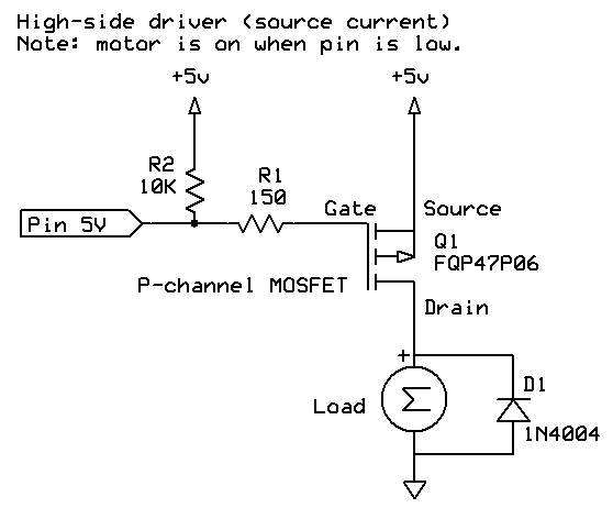
The advantage of a low-side driver is that you can control more than the 5V on the Arduino output pin, without extra components. If you want to switch "high side" (that is, to source current) then an extra transistor is required, as described below.
MOSFET efficiency
A MOSFET is quite efficient, when turned fully on or fully off. When fully off, it presents a very high resistance between drain and source. When fully on, it presents a very low resistance (RDSOn).
Because of the low resistance when turned on, there is only a small voltage drop between drain and source, and thus only a low amount of power is consumed in the transistor (and thus turned into heat).
For use with 5V circuits you need a so-called logic-level MOSFET which lets it be turned on largely or fully by 5V between Gate and Source (this is called VGS on the datasheet).
Gate resistor
A resistor between the output pin and the MOSFET gate limits the surge of current into the gate when the MOSFET is turned on by program logic. There is a very lengthy discussion about this on the Arduino forum: Myth: "You must have a gate resistor".
In the example given in the schematic, the 150 ohm resistor (R1) would limit current to 33 mA, even when presented with a short-circuit:
I = E / R
I = 5 / 150
I = 0.033  (33 mA)
Too large a resistor, however, would slow down the turning on or off the MOSFET, and thus it would be operating in the non-saturated region for longer, which increases the RDS value, causing the MOSFET to get hotter.
According to my calculations the turn-on time would be 2.2RC and thus using an example of 1350 pF input capacitance, and 150 ohm gate resistor, it would take:
2.2 * 1350e-12 * 150 = 4.455e-007 (0.0000004455) = 446 nS
See Wikipedia - RC time constant
Thus it would turn on in 446 nS which is probably acceptable.
Pull-down resistor
In the schematic above R2 (10k) keeps the Gate at zero volts if the Arduino pin is not configured for output, this keeps the MOSFET off if the processor is booting and has not yet set the pins correctly.
Fly-back diode
In the schematic above D1 is wired across the coil of the motor to prevent reverse EMF from damaging the MOSFET. For non-inductive loads (eg. LEDs) this diode would not be necessary. A fast switching diode (eg. 1N4001) or Schottky diode would be appropriate here.
Possible alternatives would be:
- Transient-voltage-suppression diode
- MOV (metal-oxide varistor)
- Avalanche diode
- Snubber diode
- Schottky diode
Heat calculations
To work out if the MOSFET can handle the current you are planning to use (and whether or not to use a heat-sink) first you calculate the power used, based on RDSOn for the VGS voltage that you are planning to use.
For example, RDSOn at VGS = 5V, might be quoted as 0.035 ohms.
The formula for power is
Power = I2R
So, let's say the motor draws 2 amps, it would be:
Power = (2)2 * 0.035 = 0.140 (140 mW)
Now we need to look on the datasheet for the "Thermal Resistance Junction to Ambient" (RØJA). In my example (RFP30N06LE) it is given as 80 °C/W.
So we multiply that by the number of watts, like this:
0.140 * 80 = 11.2 (degrees)
If we assume ambient is 25 °C then that means the junction temperature will be:
25 + 11.2 = 36.2 °C
This must be less than the maximum quoted junction temperature (TJmax), which if not quoted we can assume to be around 150 °C.
Check voltages
We would also check that we are operating within quoted voltage ranges. For example, VDS is the drain to source voltage. In the case of the RFP30N06LE that is 60V, so using it with a 12V supply is well within spec.
We would also check the continuous drain current (ID). In this case the MOSFET is rated at 30A, and we are planning to use 2 amps, so this is OK as well.