[Home] [Downloads] [Search] [Help/forum]


Register forum user name Search FAQ

Gammon Forum

[Folder]  Entire forum
-> [Folder]  Electronics
. -> [Folder]  Microprocessors
. . -> [Subject]  Driving motors, lights, etc. from an Arduino output pin

Driving motors, lights, etc. from an Arduino output pin

Postings by administrators only.

[Refresh] Refresh page


Posted by Nick Gammon   Australia  (22,975 posts)  [Biography] bio   Forum Administrator
Date Fri 30 Jan 2015 03:25 AM (UTC)

Amended on Tue 03 Feb 2015 02:43 AM (UTC) by Nick Gammon

Message
This page can be quickly reached from the link: http://www.gammon.com.au/motors


Introduction


Arduino output pins are generally rated at 20 mA continuous, with an absolute maximum rating of 40 mA. Therefore your circuit designs should not attempt to rely on driving a device needing more than 20 mA. Also, there is a limit to the total amount that can be driven at once. For example, if you are driving 20 output pins you cannot drive 20 x 20 mA (400 mA) because (depending on the exact chip) you may be limited to a total of 200 mA, and groups of pins are limited to 100 mA for the group.

MOSFET driver


A commonly-used technique is to use a MOSFET to drive loads, and in particular an N-channel MOSFET. An N-channel MOSFET is used as a "low side" driver, that is, it is designed to "sink" current.

Schematic


The advantage of a low-side driver is that you can control more than the 5V on the Arduino output pin, without extra components. If you want to switch "high side" (that is, to source current) then an extra transistor is required, as described below.

MOSFET efficiency


A MOSFET is quite efficient, when turned fully on or fully off. When fully off, it presents a very high resistance between drain and source. When fully on, it presents a very low resistance (RDSOn).

Because of the low resistance when turned on, there is only a small voltage drop between drain and source, and thus only a low amount of power is consumed in the transistor (and thus turned into heat).

For use with 5V circuits you need a so-called logic-level MOSFET which lets it be turned on largely or fully by 5V between Gate and Source (this is called VGS on the datasheet).

Gate resistor


A resistor between the output pin and the MOSFET gate limits the surge of current into the gate when the MOSFET is turned on by program logic. There is a very lengthy discussion about this on the Arduino forum: Myth: "You must have a gate resistor".

In the example given in the schematic, the 150 ohm resistor (R1) would limit current to 33 mA, even when presented with a short-circuit:


I = E / R
I = 5 / 150
I = 0.033  (33 mA)


Too large a resistor, however, would slow down the turning on or off the MOSFET, and thus it would be operating in the non-saturated region for longer, which increases the RDS value, causing the MOSFET to get hotter.

According to my calculations the turn-on time would be 2.2RC and thus using an example of 1350 pF input capacitance, and 150 ohm gate resistor, it would take:


2.2 * 1350e-12 * 150 = 4.455e-007 (0.0000004455) = 446 nS


See Wikipedia - RC time constant

Thus it would turn on in 446 nS which is probably acceptable.

Pull-down resistor


In the schematic above R2 (10k) keeps the Gate at zero volts if the Arduino pin is not configured for output, this keeps the MOSFET off if the processor is booting and has not yet set the pins correctly.

Fly-back diode


In the schematic above D1 is wired across the coil of the motor to prevent reverse EMF from damaging the MOSFET. For non-inductive loads (eg. LEDs) this diode would not be necessary. A fast switching diode (eg. 1N4001) or Schottky diode would be appropriate here.

Possible alternatives would be:


Heat calculations


To work out if the MOSFET can handle the current you are planning to use (and whether or not to use a heat-sink) first you calculate the power used, based on RDSOn for the VGS voltage that you are planning to use.

For example, RDSOn at VGS = 5V, might be quoted as 0.035 ohms.

The formula for power is


Power = I2R


So, let's say the motor draws 2 amps, it would be:


Power = (2)2 * 0.035 = 0.140 (140 mW)


Now we need to look on the datasheet for the "Thermal Resistance Junction to Ambient" (RØJA). In my example (RFP30N06LE) it is given as 80 °C/W.

So we multiply that by the number of watts, like this:


0.140 * 80 = 11.2  (degrees)


If we assume ambient is 25 °C then that means the junction temperature will be:


25 + 11.2 = 36.2 °C


This must be less than the maximum quoted junction temperature (TJmax), which if not quoted we can assume to be around 150 °C.

Check voltages


We would also check that we are operating within quoted voltage ranges. For example, VDS is the drain to source voltage. In the case of the RFP30N06LE that is 60V, so using it with a 12V supply is well within spec.

We would also check the continuous drain current (ID). In this case the MOSFET is rated at 30A, and we are planning to use 2 amps, so this is OK as well.

- Nick Gammon

www.gammon.com.au, www.mushclient.com
[Go to top] top

Posted by Nick Gammon   Australia  (22,975 posts)  [Biography] bio   Forum Administrator
Date Reply #1 on Fri 30 Jan 2015 03:25 AM (UTC)

Amended on Fri 31 Dec 2021 12:27 AM (UTC) by Nick Gammon

Message
High side driver


The circuit above was for a low-side driver, one that would "sink" current. At times, though, we want to "source" current, which requires a high-side driver. This is easy enough if we only want to control 5V, in which case we can connect the MOSFET up like this:


Things are backwards however, as we are using a P-channel MOSFET. It is off when the Gate is the same voltage as the Source (VGS = 0), which means that we have to output 5V (HIGH) from the Arduino to turn the MOSFET off. To turn it on we need -5V at the Gate (relative to the Source) so we need to output 0V (LOW) from the Arduino to turn the MOSFET on.

Once again there is a current-limiting resistor (R1) of 150 ohms, to limit the Arduino output pin current, and a pull-up resistor (R2) to make sure that the MOSFET is off if the Arduino pin is not configured as an output.


Things get more complicated if we need to source more than 5V, because to turn the MOSFET on we have to have a VGS of -5V or more (the Gate needs to be -5 relative to the Source, which is the opposite compared to an N-channel MOSFET). To turn it off we need to be able to set VGS to zero. So, for example, if we need to source 12V then to turn the MOSFET off we have to present 12V at the Gate. This can't be done with the Arduino output pin. To achieve this, we need a "helper" transistor, like this:


The transistor switches the 12V from our power supply on or off, based on the Arduino output pin. The 1k resistor (R1) limits the base current to the transistor.

There would be about a 0.95V drop over the base/emitter junction (VBE(sat)), so the current through base (IBE) would be:


(5 - 0.95) / 1000  = 0.00405 (4.05 mA)


The current flow of 4.05 mA is acceptable to both the Arduino output pin and the transistor. We will reckon on a gain of around 10 at saturation so that means it can sink 40.5 mA through R2.

In order for R2 to drop 12V the current through it must be:


12/1000 = 0.012  (12 mA)


We calculated above that the transistor can sink 40.5 mA so this is acceptable.

Next we need to calculate the power dissipated by the transistor which will be the sum of the base-emitter power and the collector-emitter power.


power = (VBE(sat) * IBE) + (VCE(sat) * ICE)

VBE(sat) = 0.95  (from datasheet)
5V (at pin) - VBE(sat) / 1k  =  (5 - 0.95) / 1000 = 0.00405 (4.05 mA)
VCE(sat) = 0.2 (from datasheet)
Sink 12V through the 1k resistor = 12 / 1000 = 0.012 (12 mA)
RØJA = 200 °C/W (from datasheet)

Power =  (0.95 * 0.00405) + (0.2 * 0.012) = 0.00625 (6.25 mW)
Heat gain =  0.00625 * 200 = 1.25 °C


Once again we have a flyback diode to protect the MOSFET if it is driving an inductive load.

To turn the MOSFET on we output a HIGH signal from the Arduino, which means the transistor conducts, and sinks the Gate of the MOSFET to ground, effectively making it -12V compared to the Source.

To turn the MOSFET off, we output a LOW signal from the Arduino, thus Q1 does not conduct, and therefore the 1k resistor (R2) pulls the Gate to 12V. Now Gate and Source are at 12V so the MOSFET is off (VGS = 0).


Switching higher voltages


Things get more complicated again if we want to switch more than about 12 V, because we need to keep VGS within the specified range of VGS(max) for the MOSFET. Check the datasheet, but VGS(max) may be in the order of ± 15 V, possibly ± 25 V.

To do this we need to clamp the VGS voltage with a 10 V zener diode, shown below as D2:


We know that we will have around 4.3 V on the emitter of Q1 (5 V - 0.7 V drop from base to emitter) thus the current through the emitter must be:


4.7 / 330 = 14.2 mA


If the main supply voltage is off, then that entire 14.2 mA will be provided by the Arduino output pin, which is within tolerance for it.

However if the main supply (shown above as 24 V) is on, then most of the current will flow from the collector. This is known as the "alpha" ratio, caculated as:


α = β / (1 + β)


Since β will be about 100, then we have:


α = 100 / 101 = 0.99


In that case the base current will be 142 µA and the collector current will be 14.06 mA.

That should be enough current to "activate" the zener diode, causing it to maintain a voltage drop of 10 V over VGS.

The 1 k resistor (R2) is to pull the gate quickly back up to the supply voltage if the transistor is off.


Switching time


It is important that the MOSFET be switched on and off quickly, as it has low power dissipation when fully off (ie. no current flowing) or fully on (when there is a low resistance between gate and drain). At other times the power dissipation will be higher, and the part may get hot.

This won't be an issue for low-switching speeds (eg. turning garden lights on and off, or a fish feeder) but becomes an issue when doing PWM (pulse-width modulation) where you may be switching on and off many times a second.

The analogWrite function on the Atmega328-based Arduinos runs by default at 490 Hz. Tests indicate that the circuit above will take about 1 µS to switch on and 8 µS to switch off (if using the high-side driver) and 1 µS to switch both on and off if using the low-side driver.

This is one of the reasons for choosing a reasonably low value for R2 in the high-side driver. We rely on R2 to pull the gate of the MOSFET high when the transistor is turned off, and we need that done as quickly as reasonably possible. We could potentially use a lower value resistor for R2 (eg. 470 ohms) to increase the switching speed, but then Q1 (the driver transistor) has to switch higher currents, and we need to watch that this transistor (Q1) does not get too hot.

Where does the motor power come from?


Another point which can be initially confusing is expecting the Arduino board to provide enough power to run a motor, or lots of LEDs. It won't, basically. The power supply on the Arduino is rated with enough capacity to drive the chips on the board itself, with a little over for extra chips like clocks, SD cards, etc.

It is not intended to drive a 3 amp electric motor.

In this case you have a separate power supply (maybe a battery, maybe a plug-pack) which is the "+5V" or "+12V" on the circuits above.

However it is important to connect the grounds. That is, connect the ground wire from the battery or plug-pack to the ground wire on the Arduino. That way they have a common "reference voltage".

- Nick Gammon

www.gammon.com.au, www.mushclient.com
[Go to top] top

Posted by Nick Gammon   Australia  (22,975 posts)  [Biography] bio   Forum Administrator
Date Reply #2 on Fri 30 Jan 2015 03:35 AM (UTC)

Amended on Sat 31 Jan 2015 12:08 AM (UTC) by Nick Gammon

Message
More information


AddOhms' YouTube video about MOSFETs: MOSFETs and How to Use Them

Mike Cook's tutorial on power: Power & Heat

Wikipedia: MOSFET

Afrotechmods: Transistor / MOSFET tutorial and What is PWM? Pulse Width Modulation tutorial!

Also see the links above regarding flyback protection and snubber diodes.

Terminology


Voltages, currents and resistances on datasheets are often given like this: VGS

That means V (voltage) between G (gate) and S (source).

They may also have a condition attached, eg.

RDS(on)

In that case this means R (resistance) between D (drain) and S (source) when the MOSFET is turned on. The datasheet may specify different values for different conditions, eg. RDS(on) when VGS = 5V. In other words, the resistance between Drain and Source when there is 5V between Gate and Source.

- Nick Gammon

www.gammon.com.au, www.mushclient.com
[Go to top] top

Posted by Nick Gammon   Australia  (22,975 posts)  [Biography] bio   Forum Administrator
Date Reply #3 on Tue 03 Feb 2015 02:48 AM (UTC)

Amended on Fri 07 Aug 2015 04:29 AM (UTC) by Nick Gammon

Message
BJT transistor driver


Moving on from MOSFETs, let's look at using BJTs (Bipolar Junction Transistors) as switches.

The advantages of BJTs are that they are small and cheap. The disadvantages are that they are current-driven rather than voltage-driven like MOSFETs, and in general are more suited to low-power applications, like driving a few LEDs, a small motor or a relay.


This circuit is similar to the "low side" MOSFET driver described above. The emitter of the transistor is connected to Ground, so it "sinks" current. The transistor is an NPN transistor. A similar and common part would be the BC546/547/548 transistors.

Two important calculations here are the two resistors. RB - the Base resistor, and RL - the Load resistor.

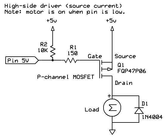
Some loads (like motors) will not need a load resistor as they will be naturally current limited (however they may require a fly-back diode as described above).

Calculate the load resistor


Let's assume that we want to drive the LED with 20 mA, and we establish that the LED has a forward voltage drop of 1.7V (from the datasheet, or by measurement).

We can see from the datasheet for our transistor that (in this case) that the Collector−Emitter Saturation Voltage VCE(sat) is around 0.4V with a load of 15 mA.

Thus the voltage drop over the resistor will be:


V = 5 - 1.7 - 0.4 = 2.9 V


And since we want 20 mA to flow we can use Ohm's Law to calculate RL:


RL = 2.9 / 0.020 = 145 ohms


So we'll use a standard value of 150 ohms for RL.

Power dissipated by this resistor will be I2R, which would be:


PL = 0.0202 * 150 = 0.060 (60 mW)


Thus a 1/8 watt resistor would be fine.

Calculate the base resistor


We want to fully "saturate" (turn on) the transistor, so a fairly substantial amount of current will be required. The datasheet quotes the "Collector−Emitter Saturation Voltage" as being one when IC is 150 mA and IB is 15 mA, thus we can deduce that (at those current levels) the transistor will only have a gain of 10 (that is, 150/15) when saturated, thus we would require a current of 2 mA to flow through the Base to the Emitter (that is, 20mA / 10).

The datasheet says that the Base−Emitter Saturation Voltage VBE(sat) is around 1.3V with a load of 15 mA, thus the voltage drop over the resistor will be:


V = 5 - 1.3 = 3.7 V


Since we want 2 mA to flow we can use Ohm's Law to calculate RB:


RB = 3.7 / 0.002 = 1850 ohms


Thus a 2k resistor should be satisfactory.

Power dissipated by this resistor will be I2R, which would be:


PB = 0.0022 * 1600 = 0.008 (8 mW)


Thus a 1/8 watt resistor would be fine here too.

Transistor power dissipation


Next we need to calculate the power dissipated by the transistor which will be the sum of the base-emitter power and the collector-emitter power.


power = (VBE(sat) * IBE) + (VCE(sat) * ICE)

VBE(sat) = 1.3  (from datasheet)
IBE = 0.002 (2 mA - as calculated above)
VCE(sat) = 0.4 (from datasheet)
ICE = 0.020 (20 mA - as calculated above)
RØJA = 200 °C/W (from datasheet)

Power =  (1.3 * 0.002) + (0.4 * 0.020) = 0.0106 (10.6 mW)
Heat gain =  0.0106 * 200 = 2.12 °C


Calculations in Lua


-- standard values for 5% resistors
standardValues = {
  1.0,  1.1,  1.2,  1.3,  1.5,  1.6,  1.8,  2.0,  2.2,  2.4,  2.7,  3.0,
  3.3,  3.6,  3.9,  4.3,  4.7,  5.1,  5.6,  6.2,  6.8,  7.5,  8.2,  9.1,
  10.0 }

-- turn a resistance into the next highest standard value (5%)
function makeStandardValue (value)
  local exponent = math.floor (math.log10 (value))
  local fraction = 10^(math.log10 (value) - exponent)
  for k, v in ipairs (standardValues) do
    if v > fraction then
      return v * 10^exponent
    end -- if
  end -- for
  error "Shouldn't get here"
end -- function makeStandardValue


-- parameters

-- the transistor (from the datasheet)
VBEsat = 1.3        -- volts (Base-Emitter Saturation Voltage)
VCEsat = 0.4        -- volts (Collector-Emitter Saturation Voltage)
RthetaJA = 200      -- °C/W (Thermal Resistance, Junction to Ambient)

-- the load
Vload = 5           -- volts (load supply voltage on the motor / LED)
LEDforward = 1.2    -- LED forward voltage (zero if no LED)
ICE = 0.02          -- current through load (collector) in amps

-- how we are turning on the transistor
Venable = 5         -- volts to enable the transistor (eg. Arduino pin)

-- calculate RL (load resistor)
VL = Vload - LEDforward - VCEsat
RL = makeStandardValue (VL / ICE)
PL = ICE^2 * RL

print (string.rep ("-", 10) .. " Load resistor " .. string.rep ("-", 10) )
print ("Voltage over RL =", VL .. " V")
print ("RL =", RL .. " ohms")
print ("RL power =", PL .. " watts (" .. math.floor (PL * 1000) .. " mW)")

-- calculate RB (base resistor)

print (string.rep ("-", 10) .. " Base resistor " .. string.rep ("-", 10) )
VB = Venable - VBEsat
IBE = ICE / 10  -- rule of thumb, use 1/10 of collector current for full saturation
RB = makeStandardValue (VB / IBE)
PB = IBE^2 * RB
print ("RB =", RB .. " ohms")
print ("RB power =", PB .. " watts (" .. math.floor (PB * 1000) .. " mW)")


-- calculate transistor power

print (string.rep ("-", 10) .. " Transistor power " .. string.rep ("-", 10) )
Power =  (VBEsat * IBE) + (VCEsat * ICE) 
print ("Power =", Power * 1000, "mW")  
Heatgain =  Power  * RthetaJA 
print ("Heat =", Heatgain, "degrees C") 


Summary


The net result here is that we are using 2 mA from the Arduino output pin to control a 20 mA LED. Now, an Arduino can directly drive 20 mA, however the workings above should let you calculate resistors for other loads.

- Nick Gammon

www.gammon.com.au, www.mushclient.com
[Go to top] top

The dates and times for posts above are shown in Universal Co-ordinated Time (UTC).

To show them in your local time you can join the forum, and then set the 'time correction' field in your profile to the number of hours difference between your location and UTC time.


119,519 views.

Postings by administrators only.

[Refresh] Refresh page

Go to topic:           Search the forum


[Go to top] top

Quick links: MUSHclient. MUSHclient help. Forum shortcuts. Posting templates. Lua modules. Lua documentation.

Information and images on this site are licensed under the Creative Commons Attribution 3.0 Australia License unless stated otherwise.

[Home]


Written by Nick Gammon - 5K   profile for Nick Gammon on Stack Exchange, a network of free, community-driven Q&A sites   Marriage equality

Comments to: Gammon Software support
[RH click to get RSS URL] Forum RSS feed ( https://gammon.com.au/rss/forum.xml )

[Best viewed with any browser - 2K]    [Hosted at HostDash]