A cheap and simple way of expanding your processor's output capability is by using a "shift register" like the 74HC595 described here.
Tip:
A complementary device is the 74HC165 input shift register mentioned in the post below:
http://www.gammon.com.au/forum/?id=11979
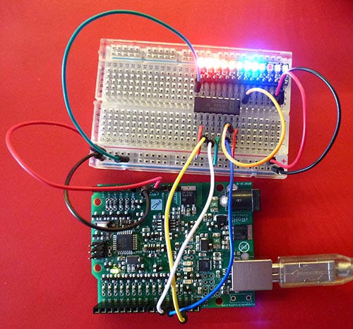
Example of it in use, displaying 8 LEDs:
The pin-outs for the 74HC595 are:

You can "daisy-chain" them to connect multiple ones together, thus giving you 8, 16, 24, 32 or more extra output ports, by simply connecting the "overflow" bit of one register to the "data in" of the next.

The 10K pull-down resistor on the SS (Slave Select) is designed to keep the registers from clocking in bits while the main processor is booting, and the SS line might be "floating" and in an indeterminate state.
Master reset
I have tied /MR (master reset) high, so the chips are never in a reset state. If you needed to reset them from time to time you could parallel up those pins and connect them to a processor pin.
Output enable
I have tied /OE (output enable) low, so the chips are always in output mode. If you needed to have them high impedance (neither high nor low) you could parallel up those pins and connect them to a processor pin (eg, D9).
It's extremely simple to send data to the shift register. You can use SPI to do the hard work:
More details about SPI here:
http://gammon.com.au/spi
The call to SPI.transfer() sends a byte to the register (a bit at a time) and then bringing the LATCH (otherwise known as SS or ST) line high causes the data to be transferred from the register's internal memory to the output pins.
Pin connections for Uno and similar:
Pin connections for Mega2560:
To send more than 8 bits you simply transfer more than once before latching. So if you had four devices chained together you might do this:
Once more than 8 bits arrive at the first register they "overflow" out the Q7' port and go into the DS (data in) port of the next device. And so on, if there are more than 16 bits. So what eventually happens is that the 0xAB byte ends up in the device the furthest down the chain. Effectively:
Where "xx" represents whatever was there before.
Thus the furthest device down the chain gets whatever byte was sent first.
SPI is very fast, it takes around 3 uS to send one byte, so sending all 4 bytes would only take around 12 uS.
The code below uses "bit banged" SPI rather than the hardware SPI. This lets you use any pins for the shift register, perhaps keeping the SPI pins free for an SD card or other device.
You need to install the "bitBangedSPI" library (link below) into your libraries folder:
http://www.gammon.com.au/Arduino/bitBangedSPI.zip
Note, the LEDs shown have built-in current limiting resistors. You would not normally put LEDs directly onto the output of the 595 chip, as the current drain would be too high.
Tip:
A complementary device is the 74HC165 input shift register mentioned in the post below:
http://www.gammon.com.au/forum/?id=11979
Example of it in use, displaying 8 LEDs:
Pin outs
The pin-outs for the 74HC595 are:
You can "daisy-chain" them to connect multiple ones together, thus giving you 8, 16, 24, 32 or more extra output ports, by simply connecting the "overflow" bit of one register to the "data in" of the next.
Schematic
The 10K pull-down resistor on the SS (Slave Select) is designed to keep the registers from clocking in bits while the main processor is booting, and the SS line might be "floating" and in an indeterminate state.
Master reset
I have tied /MR (master reset) high, so the chips are never in a reset state. If you needed to reset them from time to time you could parallel up those pins and connect them to a processor pin.
Output enable
I have tied /OE (output enable) low, so the chips are always in output mode. If you needed to have them high impedance (neither high nor low) you could parallel up those pins and connect them to a processor pin (eg, D9).
Program code
It's extremely simple to send data to the shift register. You can use SPI to do the hard work:
#include <SPI.h>

const byte LATCH = 10;

void setup ()
{
  SPI.begin ();
}  // end of setup

byte c;
void loop ()
{
  c++;
  digitalWrite (LATCH, LOW);
  SPI.transfer (c);
  digitalWrite (LATCH, HIGH);
  delay (20);
}  // end of loop
More details about SPI here:
http://gammon.com.au/spi
The call to SPI.transfer() sends a byte to the register (a bit at a time) and then bringing the LATCH (otherwise known as SS or ST) line high causes the data to be transferred from the register's internal memory to the output pins.
Pin connections
Pin connections for Uno and similar:
// Chip pin 14 (DS) goes to MOSI  (D11)
// Chip pin 11 (SH) goes to SCK   (D13)
// Chip pin 12 (ST) goes to SS    (D10)  (or any other pin by changing LATCH)
Pin connections for Mega2560:
// Chip pin 14 (DS) goes to MOSI  (D51)
// Chip pin 11 (SH) goes to SCK   (D52)
// Chip pin 12 (ST) goes to SS    (D10)  (or any other pin by changing LATCH)
Daisy chaining
To send more than 8 bits you simply transfer more than once before latching. So if you had four devices chained together you might do this:
  digitalWrite (LATCH, LOW);
  SPI.transfer (0xAB);
  SPI.transfer (0xCD);
  SPI.transfer (0xEF);
  SPI.transfer (0x42);
  digitalWrite (LATCH, HIGH);
Once more than 8 bits arrive at the first register they "overflow" out the Q7' port and go into the DS (data in) port of the next device. And so on, if there are more than 16 bits. So what eventually happens is that the 0xAB byte ends up in the device the furthest down the chain. Effectively:
Sent data     Data in devices

(nothing)     xx xx xx xx
  AB          AB xx xx xx
  CD          CD AB xx xx
  EF          EF CD AB xx
  42          42 EF CD AB

(latch)       Commit to output pins on all devices
Where "xx" represents whatever was there before.
Thus the furthest device down the chain gets whatever byte was sent first.
SPI is very fast, it takes around 3 uS to send one byte, so sending all 4 bytes would only take around 12 uS.
Bit-banged SPI code
The code below uses "bit banged" SPI rather than the hardware SPI. This lets you use any pins for the shift register, perhaps keeping the SPI pins free for an SD card or other device.
#include <bitBangedSPI.h>

bitBangedSPI bbSPI (8, bitBangedSPI::NO_PIN, 9);  // MOSI, MISO, SCK

const byte LATCH = 10;

void setup ()
{
  bbSPI.begin ();
  pinMode (LATCH, OUTPUT);
}  // end of setup

byte c;
void loop ()
{
  c++;
  digitalWrite (LATCH, LOW);
  bbSPI.transfer (c);
  digitalWrite (LATCH, HIGH);
  delay (20);
}  // end of loop
You need to install the "bitBangedSPI" library (link below) into your libraries folder:
http://www.gammon.com.au/Arduino/bitBangedSPI.zip
Note, the LEDs shown have built-in current limiting resistors. You would not normally put LEDs directly onto the output of the 595 chip, as the current drain would be too high.
