[Home] [Downloads] [Search] [Help/forum]


Register forum user name Search FAQ

Gammon Forum

[Folder]  Entire forum
-> [Folder]  Electronics
. -> [Folder]  Microprocessors
. . -> [Subject]  Using a 74HC595 output shift register as a port-expander

Using a 74HC595 output shift register as a port-expander

Postings by administrators only.

[Refresh] Refresh page


Posted by Nick Gammon   Australia  (22,973 posts)  [Biography] bio   Forum Administrator
Date Tue 31 Jan 2012 08:33 PM (UTC)

Amended on Fri 10 Oct 2014 12:06 AM (UTC) by Nick Gammon

Message
A cheap and simple way of expanding your processor's output capability is by using a "shift register" like the 74HC595 described here.


Tip:

A complementary device is the 74HC165 input shift register mentioned in the post below:

http://www.gammon.com.au/forum/?id=11979


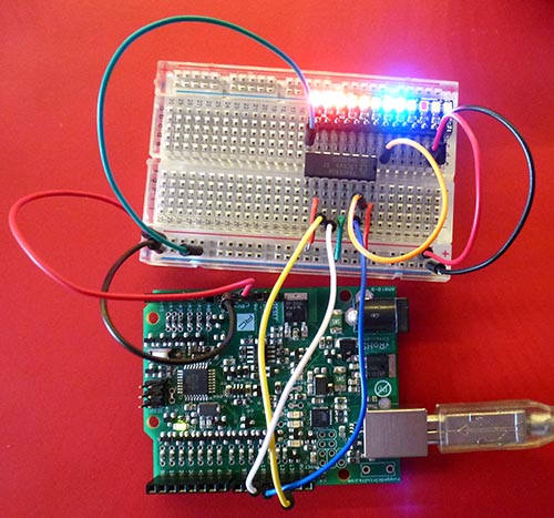
Example of it in use, displaying 8 LEDs:


Pin outs


The pin-outs for the 74HC595 are:


You can "daisy-chain" them to connect multiple ones together, thus giving you 8, 16, 24, 32 or more extra output ports, by simply connecting the "overflow" bit of one register to the "data in" of the next.

Schematic


The 10K pull-down resistor on the SS (Slave Select) is designed to keep the registers from clocking in bits while the main processor is booting, and the SS line might be "floating" and in an indeterminate state.

Master reset

I have tied /MR (master reset) high, so the chips are never in a reset state. If you needed to reset them from time to time you could parallel up those pins and connect them to a processor pin.

Output enable

I have tied /OE (output enable) low, so the chips are always in output mode. If you needed to have them high impedance (neither high nor low) you could parallel up those pins and connect them to a processor pin (eg, D9).

Program code


It's extremely simple to send data to the shift register. You can use SPI to do the hard work:


#include <SPI.h>

const byte LATCH = 10;

void setup ()
{
  SPI.begin ();
}  // end of setup

byte c;
void loop ()
{
  c++;
  digitalWrite (LATCH, LOW);
  SPI.transfer (c);
  digitalWrite (LATCH, HIGH);
  delay (20);
}  // end of loop


More details about SPI here:

http://gammon.com.au/spi

The call to SPI.transfer() sends a byte to the register (a bit at a time) and then bringing the LATCH (otherwise known as SS or ST) line high causes the data to be transferred from the register's internal memory to the output pins.

Pin connections


Pin connections for Uno and similar:


// Chip pin 14 (DS) goes to MOSI  (D11)
// Chip pin 11 (SH) goes to SCK   (D13)
// Chip pin 12 (ST) goes to SS    (D10)  (or any other pin by changing LATCH)


Pin connections for Mega2560:


// Chip pin 14 (DS) goes to MOSI  (D51)
// Chip pin 11 (SH) goes to SCK   (D52)
// Chip pin 12 (ST) goes to SS    (D10)  (or any other pin by changing LATCH)


Daisy chaining


To send more than 8 bits you simply transfer more than once before latching. So if you had four devices chained together you might do this:


  digitalWrite (LATCH, LOW);
  SPI.transfer (0xAB);
  SPI.transfer (0xCD);
  SPI.transfer (0xEF);
  SPI.transfer (0x42);
  digitalWrite (LATCH, HIGH);


Once more than 8 bits arrive at the first register they "overflow" out the Q7' port and go into the DS (data in) port of the next device. And so on, if there are more than 16 bits. So what eventually happens is that the 0xAB byte ends up in the device the furthest down the chain. Effectively:


Sent data     Data in devices

(nothing)     xx xx xx xx
  AB          AB xx xx xx
  CD          CD AB xx xx
  EF          EF CD AB xx
  42          42 EF CD AB

(latch)       Commit to output pins on all devices


Where "xx" represents whatever was there before.

Thus the furthest device down the chain gets whatever byte was sent first.

SPI is very fast, it takes around 3 uS to send one byte, so sending all 4 bytes would only take around 12 uS.

Bit-banged SPI code


The code below uses "bit banged" SPI rather than the hardware SPI. This lets you use any pins for the shift register, perhaps keeping the SPI pins free for an SD card or other device.


#include <bitBangedSPI.h>

bitBangedSPI bbSPI (8, bitBangedSPI::NO_PIN, 9);  // MOSI, MISO, SCK

const byte LATCH = 10;

void setup ()
{
  bbSPI.begin ();
  pinMode (LATCH, OUTPUT);  
}  // end of setup

byte c;
void loop ()
{
  c++;
  digitalWrite (LATCH, LOW);
  bbSPI.transfer (c);
  digitalWrite (LATCH, HIGH);
  delay (20);
}  // end of loop


You need to install the "bitBangedSPI" library (link below) into your libraries folder:

http://www.gammon.com.au/Arduino/bitBangedSPI.zip


Note, the LEDs shown have built-in current limiting resistors. You would not normally put LEDs directly onto the output of the 595 chip, as the current drain would be too high.

- Nick Gammon

www.gammon.com.au, www.mushclient.com
[Go to top] top

Posted by Nick Gammon   Australia  (22,973 posts)  [Biography] bio   Forum Administrator
Date Reply #1 on Wed 02 May 2012 06:11 AM (UTC)

Amended on Tue 26 Nov 2013 01:16 AM (UTC) by Nick Gammon

Message
Example of 4 shift register chips breadboarded with 32 LEDs:


There are about 8 x 0.1 uF decoupling capacitors there between +5V and Gnd, to keep it all stable.

There are 1K resistors on the board in series with the LEDs.


Video of this in action:


Sketch to make the LEDs light up in sequence:


// Demo sketch to turn sequence up and down bits in 4 shift registers
// Author: Nick Gammon
// Date: 2 May 2012

#include <SPI.h>

const byte LATCH = 10;

const byte numberOfChips = 4;

byte LEDdata [numberOfChips];  // initial pattern

void refreshLEDs ()
  {
  digitalWrite (LATCH, LOW);
  for (byte i = 0; i < numberOfChips; i++)
    SPI.transfer (LEDdata [i]); 
  digitalWrite (LATCH, HIGH);
  } // end of refreshLEDs
  

void setup ()
{
  SPI.begin ();
}  // end of setup


void showPattern (const unsigned int p1, const unsigned int p2)
  {
  LEDdata [0] = highByte (p1);
  LEDdata [1] = lowByte (p1);
  LEDdata [2] = highByte (p2);
  LEDdata [3] = lowByte (p2);
  refreshLEDs ();
  delay (30);
  } // end of showPattern
  
void loop ()
{
unsigned int pattern;
 
  pattern = 1;
  for (int i = 0; i < 16; i++)
    {
    showPattern (pattern, pattern);
    pattern <<= 1;
    }

  pattern = 0x8000;
  for (int i = 0; i < 16; i++)
    {
    showPattern (pattern, pattern);
    pattern >>= 1;
    }    

  pattern = 1;
  for (int i = 0; i < 16; i++)
    {
    showPattern (~pattern, ~pattern);
    pattern <<= 1;
    }

  pattern = 0x8000;
  for (int i = 0; i < 16; i++)
    {
    showPattern (~pattern, ~pattern);
    pattern >>= 1;
    }    
    
}  // end of loop


Another sketch that lets you choose from the serial monitor which LED to turn on.

[EDIT] However see further down for a more sophisticated version.


// Demo sketch to turn on or off bits in a set of shift registers
// Author: Nick Gammon
// Date: 2 May 2012

#include <SPI.h>

const byte LATCH = 10;

const byte numberOfChips = 4;
const byte maxLEDs = numberOfChips * 8;

byte LEDdata [numberOfChips] = { 0 };  // initial pattern

void refreshLEDs ()
  {
  digitalWrite (LATCH, LOW);
  for (int i = numberOfChips - 1; i >= 0; i--)
    SPI.transfer (LEDdata [i]); 
  digitalWrite (LATCH, HIGH);
  } // end of refreshLEDs
  

// how much serial data we expect before a newline
const unsigned int MAX_INPUT = 10;

void setup ()
{
  Serial.begin(115200);
  SPI.begin ();
  refreshLEDs ();
} // end of setup

// here to process incoming serial data after a terminator received
void process_data (char * data)
  {
  Serial.print ("Got command: ");
  Serial.println (data);
  
  // C: clear all bits
  switch (toupper (data [0]))
    {
     case 'C':
        {
        for (int i = 0; i < numberOfChips; i++) 
          LEDdata [i] = 0;
        Serial.println ("All bits cleared.");
        refreshLEDs ();
        return;
        }
  
    // S: set all bits
    case 'S':
        {
        for (int i = 0; i < numberOfChips; i++) 
          LEDdata [i] = 0xFF;
        Serial.println ("All bits set.");
        refreshLEDs ();
        return;
        }
    
    // I: invert all bits
    case 'I':
        {
        for (int i = 0; i < numberOfChips; i++) 
          LEDdata [i] ^= 0xFF;
        Serial.println ("All bits inverted.");
        refreshLEDs ();
        return;
        }
    } // end of switch
  
  // otherwise: nnx 
  //   where nn is 1 to 89 and x is 0 for off, or 1 for on
  
  // check we got numbers
  for (int i = 0; i < 3; i++)
    if (!isdigit (data [i]))
      {
      Serial.println ("Did not get 3 digits.");
      return;
      }
      
  // convert first 2 digits to the LED number
  byte led = (data [0] - '0') * 10 + (data [1] - '0');
  
  // convert third digit to state (0 = off)
  byte state = data [2] - '0';  // 0 = off, otherwise on
  
  if (led > maxLEDs)
      {
      Serial.println ("LED # too high.");
      return;
      }
   
   led--;  // make zero relative
   
   // divide by 8 to work out which chip
   byte chip = led / 8;  // which chip
   
   // remainder is bit number
   byte bit = 1 << (led % 8);
   
   // turn bit on or off
   if (state)
     LEDdata [chip] |= bit;
   else
     LEDdata [chip] &= ~ bit;
  
  Serial.print ("Turning ");
  Serial.print (state ? "on" : "off");
  Serial.print (" bit ");
  Serial.print (led & 0x7, DEC);
  Serial.print (" on chip ");
  Serial.println (chip, DEC);
  
  refreshLEDs ();
  }  // end of process_data
  

void loop()
{
static char input_line [MAX_INPUT];
static unsigned int input_pos = 0;

  if (Serial.available () > 0) 
    {
    char inByte = Serial.read ();

    switch (inByte)
      {

      case '\n':   // end of text
        input_line [input_pos] = 0;  // terminating null byte
        
        // terminator reached! process input_line here ...
        process_data (input_line);
        
        // reset buffer for next time
        input_pos = 0;  
        break;
  
      case '\r':   // discard carriage return
        break;
  
      default:
        // keep adding if not full ... allow for terminating null byte
        if (input_pos < (MAX_INPUT - 1))
          input_line [input_pos++] = inByte;
        break;

      }  // end of switch

  }  // end of incoming data

  // do other stuff here like testing digital input (button presses) ...

}  // end of loop


Example commands:


C    <-- clear all LEDs
S    <-- set (turn on ) all LEDs
I    <-- invert all LEDs (turn off if on, and vice-versa)
021  <-- turn LED 02 on
020  <-- turn LED 02 off
161  <-- turn LED 16 on


Improved LED control sketch


// Example of setting, clearing, rotating LEDs connected to a 74HC595 shift register
// Author: Nick Gammon
// Date: 3rd May 2012

/*
 
 For more information see: 
 
   http://www.gammon.com.au/forum/?id=11518
 
 Baud rate: 115200
 
 Commands you can type in the serial monitor (can be upper or lower case):
 
 nnnX   where nnn is a number (1 or more digits) and X is a command
 
 Spaces are ignored. Carriage-return or linefeed terminates the current command and resets ready for a new one.
 
 nnn C  --> Clear LED nnn. If nnn is omitted, or zero, all LEDs are cleared.
 nnn S  --> Set LED nnn. If nnn is omitted, or zero, all LEDs are set.
 nnn I  --> Invert LED nnn. If nnn is omitted, or zero, all LEDs are inverted.  (if on, turned off, or vice-versa)
 
 nnn R  --> Rotate all LEDs to the right nnn positions. If nnn is omitted, default to rotate one position right. 
 nnn L  --> Rotate all LEDs to the left nnn positions. If nnn is omitted, default to rotate one position left. 
 
 nnn D  --> Set delay amount. The delay (default 100 mS) is done after each command. Can be zero for doing things quickly.
 nnn P  --> Pause for nnn milliseconds. If nnn is zero, pause for the delay amount.
   
 Examples:
 
 5s  --> turn LED 5 on
 s   --> turn all LEDs on
 7s8s9s  --> turn on LEDs 7, 8, 9
 30c --> clear LED number 30
 c   --> clear (turn off) all LEDs
 44i --> invert LED number 44 (turn on if off, or off if on)
 i   --> invert all LEDs
 R   --> rotate pattern 1 to the right (if LED 1 was on, LED 2 will be on now and so on)
 10r --> rotate pattern 10 positions to the right
 L   --> rotate pattern 1 to the left (if LED 2 was on, LED 1 will be on now and so on)
 4L  --> rotate pattern 4 positions to the left
 
 1000D --> do a delay of 1000 mS (1 second) after every command
 P   --> pause the current delay amount
 50P --> pause for 50 mS
 
 
 Change "numberOfChips" below to reflect how many 74HC595 shift registers you have connected together.

 Wiring: 
         D10 (SS) to ST_CP (pin 12) of all 74HC595 chips
         D11 (MOSI) to DS (pin 14) of the first 74HC595 chip
         D13 (SCK) to SH_CP (pin 11) of all 74HC595 chips
         
If you want to use a different SS (LATCH) pin on the processor change the LATCH constant below.        
 */


#include <SPI.h>

const byte LATCH = 10;

const byte numberOfChips = 4;
const byte maxLEDs = numberOfChips * 8;

byte LEDdata [numberOfChips] = { 0 };  // initial pattern

unsigned long delayAmount = 100;

void refreshLEDs ()
  {
  digitalWrite (LATCH, LOW);
  for (int i = numberOfChips - 1; i >= 0; i--)
    SPI.transfer (LEDdata [i]); 
  digitalWrite (LATCH, HIGH);
  } // end of refreshLEDs
  
void setup ()
  { 
  SPI.begin ();    
  Serial.begin (115200);
  Serial.println ("Starting ...");
  refreshLEDs ();  // clear all LEDs
  } // end of setup
  
// turn an LED number into the position in the array, and a bit mask
boolean getChipAndBit (unsigned int led, int & chip, byte & mask)
  {
  if (led > maxLEDs)
      {
      Serial.print ("LED ");
      Serial.print (led);
      Serial.println (" too high.");
      return true;  // error
      } // end of too high
    
   led--;  // make zero relative
   
   // divide by 8 to work out which chip
   chip = led / 8;  // which chip
   
   // remainder is bit number
   mask = 1 << (led % 8);
   
  return false;  // no error
  }  // end of getChipAndBit

// clear LED n (or all if zero)
void clearLED (const long n)
  {
  // zero means all
  if (n == 0)
    {
    for (int i = 0; i < numberOfChips; i++) 
      LEDdata [i] = 0;
    return;
    }  // end of if zero
    
  int chip;
  byte mask;
  if (getChipAndBit (n, chip, mask))
    return;  // bad number
    
  LEDdata [chip] &= ~ mask;
  }  // end of clearLED

// set LED n (or all if zero)
void setLED (const long n)
  {
  // zero means all
  if (n == 0)
    {
    for (int i = 0; i < numberOfChips; i++) 
      LEDdata [i] = 0xFF;
    return;
    }  // end of if zero
    
  int chip;
  byte mask;
  if (getChipAndBit (n, chip, mask))
    return;  // bad number
    
  LEDdata [chip] |= mask;
  }  // end of setLED

// invert LED n (or all if zero)
void invertLED (const long n)
  {
  // zero means all
  if (n == 0)
    {
    for (int i = 0; i < numberOfChips; i++) 
      LEDdata [i] ^= 0xFF;
    return;
    } // end of if zero
    
  int chip;
  byte mask;
  if (getChipAndBit (n, chip, mask))
    return;  // bad number
    
  LEDdata [chip] ^= mask;
  }  // end of invertLED
  
// set the current delay amount to n
void setDelay (const long n)
  {
  delayAmount = n;  
  }  // end of setDelay
  
// rotate pattern right (up) n positions
void rotateRight (unsigned int n)
  {
  if (n >= maxLEDs)
    {
    Serial.print ("Rotation right amount ");
    Serial.print (n);
    Serial.println (" too high.");
    return;  // error
    }  // end of if too high an amount

  // assume rotate at least once
  if (n == 0)
    n = 1;
    
  // first do whole bytes
  while (n >= 8)
    {
    byte temp = LEDdata [numberOfChips - 1];
    memmove (&LEDdata [1], &LEDdata [0], numberOfChips - 1);
    LEDdata [0] = temp;
    n -= 8;
    }  // end of more than a byte  
    
   while (n-- > 0)
    {
    // each time we carry forwards the high order bit
    // the very first time we take that bit from the highest byte
    byte oldCarry = (LEDdata [numberOfChips - 1] & 0x80) ? 1 : 0;
    
    for (int thisChip = 0; thisChip < numberOfChips; thisChip++)
      {
      byte newCarry = (LEDdata [thisChip] & 0x80) ? 1 : 0;
      LEDdata [thisChip] <<= 1;  
      LEDdata [thisChip] |= oldCarry;
      oldCarry = newCarry;
      } // end of for
    }  // end of doing each bit 
 
  }  // end of rotateRight

// rotate pattern left (down) n positions
void rotateLeft (unsigned int n)
  {
  if (n >= maxLEDs)
    {
    Serial.print ("Rotation left amount ");
    Serial.print (n);
    Serial.println (" too high.");
    return;  // error
    }  // end of if too high an amount

  // assume rotate at least once
  if (n == 0)
    n = 1;
    
  // first do whole bytes
  while (n >= 8)
    {
    byte temp = LEDdata [0];
    memmove (&LEDdata [0], &LEDdata [1], numberOfChips - 1);
    LEDdata [numberOfChips - 1] = temp;
    n -= 8;
    }  // end of more than a byte  
    
   while (n-- > 0)
    {
    // each time we carry forwards the low order bit
    // the very first time we take that bit from the lowest byte
    byte oldCarry = (LEDdata [0] & 1) ? 0x80 : 0;
    
    for (int thisChip = numberOfChips - 1; thisChip >= 0; thisChip--)
      {
      byte newCarry = (LEDdata [thisChip] & 1) ? 0x80 : 0;
      LEDdata [thisChip] >>= 1;  
      LEDdata [thisChip] |= oldCarry;
      oldCarry = newCarry;
      } // end of for
    }  // end of doing each bit 
 
  }  // end of rotateLeft
  
// pause for supplied mS, or if zero, the current delay amount
void pause (const long mS)
  {
  if (mS == 0)
    {
    if (delayAmount)
      delay (delayAmount);
    return;      
    }

  delay (mS);      
  }  // end of pause
  
void processCommand (const byte command, const long n)
  {
  switch (command)
    {
    case 'C': clearLED    (n);   break;   // Clear LED(s)
    case 'S': setLED      (n);   break;   // Set LED(s)
    case 'I': invertLED   (n);   break;   // Invert LED(s)
    case 'D': setDelay    (n);   break;   // Delay amount (mS)
    case 'P': pause       (n);   break;   // Pause for some mS
    case 'R': rotateRight (n);   break;   // Rotate right n positions
    case 'L': rotateLeft  (n);   break;   // Rotate left n positions
    
    default:
      Serial.print ("Unknown command: ");    
      Serial.println (command);
      return;
    
    }  // end of switch on command
    
  // push the new pattern out to the chips
  refreshLEDs ();
 
  // do optional delay between commands
  if (delayAmount)
    delay (delayAmount);
  
  }  // end of processCommand
  
void processInput ()
  {
  static long receivedNumber = 0;
  
  byte c = Serial.read ();
  
  switch (c)
    {
      
    // accumulate digits
    case '0' ... '9': 
      receivedNumber *= 10;
      receivedNumber += c - '0';
      break;

    default:
      Serial.print ("Unexpected input: ");    
      Serial.println (c);
      
      // fall through to start new number
      
    // carriage-return or line-feed starts new number
    case '\r':
    case '\n':
      receivedNumber = 0;
      break;
      
    case 'A' ... 'Z':
    case 'a' ... 'z':
      processCommand (toupper (c), receivedNumber);
      receivedNumber = 0;
      break;
      
    // ignore spaces
    case ' ':
      break;
    } // end of switch on received character
  }  // end of processInput
  
void loop ()
  {
  
  if (Serial.available ())
    processInput ();
    
  // do other stuff here
  } // end of loop


Example commands:


 5s  --> turn LED 5 on
 s   --> turn all LEDs on
 7s8s9s  --> turn on LEDs 7, 8, 9
 30c --> clear LED number 30
 c   --> clear (turn off) all LEDs
 44i --> invert LED number 44 (turn on if off, or off if on)
 i   --> invert all LEDs
 R   --> rotate pattern 1 to the right (if LED 1 was on, LED 2 will be on now and so on)
 10r --> rotate pattern 10 positions to the right
 L   --> rotate pattern 1 to the left (if LED 2 was on, LED 1 will be on now and so on)
 4L  --> rotate pattern 4 positions to the left
 
 1000D --> do a delay of 1000 mS (1 second) after every command
 P   --> pause the current delay amount
 50P --> pause for 50 mS


- Nick Gammon

www.gammon.com.au, www.mushclient.com
[Go to top] top

The dates and times for posts above are shown in Universal Co-ordinated Time (UTC).

To show them in your local time you can join the forum, and then set the 'time correction' field in your profile to the number of hours difference between your location and UTC time.


89,933 views.

Postings by administrators only.

[Refresh] Refresh page

Go to topic:           Search the forum


[Go to top] top

Quick links: MUSHclient. MUSHclient help. Forum shortcuts. Posting templates. Lua modules. Lua documentation.

Information and images on this site are licensed under the Creative Commons Attribution 3.0 Australia License unless stated otherwise.

[Home]


Written by Nick Gammon - 5K   profile for Nick Gammon on Stack Exchange, a network of free, community-driven Q&A sites   Marriage equality

Comments to: Gammon Software support
[RH click to get RSS URL] Forum RSS feed ( https://gammon.com.au/rss/forum.xml )

[Best viewed with any browser - 2K]    [Hosted at HostDash]